SSC JE Electrical Previous Year Question Paper With Solution and Explanation 2018-Set 2 | MES Electrical | SSC JE 2018 | SSC Junior Engineer Exam Paper “held on 24 Jan 2018”
Ques.1. Which of the following material does not allow the current to flow in it?
When an electric field is applied to a conductor, there occurs a large scale physical movement of free electrons because these are available in large numbers in Conductor.
On the other hand, if an electric field is applied to an insulator, there is hardly any movement of free electrons because these are just not available in an insulator. Plastics, wood, and rubber are examples of good insulators. Pure water is also an insulator. Tap water, however, contains salts that form ions which can move through the liquid, making it a good conductor.
The insulator is also called the dielectric. There are practically no free electrons in the dielectric. The electrons in dielectric normally remain bounds to their respective molecules.
There are some materials, called semiconductors, which are intermediate between conductors and insulators.
Superconducting materials are the materials which conduct electricity without resistance below a certain temperature. Superconductivity is one of the most exciting phenomena in Physics, because of the peculiar nature and the wide application of this phenomenon. This phenomenon of superconductivity was first discovered by a Dutch physicist, H.K. Onnes. Superconducting materials are having very good electrical and magnetic properties. Before the discovery of superconductors, it is believed that the electrical resistivity of the material becomes zero, only at the absolute temperature.
Ques.2. How much power (in W) will be dissipated by a 5 Ohm resistor in which the value of current is 2 A?
10
30
20✓
40
Given
Resistance R = 5Ω
Current I = 2 A
Power dissipated by the resistor is
P = I2R
P = 22 × 5
P = 20 watts
Ques.3. Which property of an electrical conductor opposes a change in the current?
Resistance
Capacitance
Conductance
Inductance✓
An inductor is a device which temporarily stores energy in the form of the magnetic field. It is usually a coil of wire. One of the basic property of the electromagnetism is that when you have current flowing through the wire it creates a small magnetic field around it.
One current first start to flow through the inductor a magnetic field start to expand then after some time magnetic field becomes constant then we have some energy stored in the magnetic field.
Once a constant magnetic field is generated in the Inductor, it will not change any further. As magnetic flux = N x I (Turns x Current), Inductor will draw a constant current to maintain the magnetic field.
Once current stop flowing the magnetic field start to collapse and the magnetic energy turned back into electric energy.
So when the current flowing through an inductor changes, the magnetic field also changes in the inductor and emf (electromotive force) is induced in the inductor as per Faraday’s law of electromagnetic induction.
According to Lenz’s law, the direction of electromotive force(emf) opposes the change of current that created it. V= -Lx dI/dt (rate of change of current)
So inductor opposes any change of current through them.
Ques.4. What is the resistivity (in ohms-m) of a 2 ohm cylindrical wire when the length and the diameter of the wire are 10 m and 0.4 m respectively?
0.025✓
0.0025
0.25
0.05
The resistance of the conductor is determined by the
R = ρL/A
Where
ρ = Resistivity of the conductor
L = Length of the conductor = 10 m
A = Area of the conductor = πR2 = 3.14 × 0.22 = 0.125 m2
R = Resistance = 2 Ω
Therefore the resistivity is
ρ = A × R ⁄ L
= 0.125 × 2 ⁄ 10
ρ = 0.025 Ω-m
Ques.5. Farad is the S.I units of____
Inductance
Resistance
Capacitance✓
Reluctance
The Farad is the practical and the Sl unit of capacitance. The unit, named after Michael Faraday (1791-1867), was first suggested by Latimer Clark in 1867. The capacitor has a capacitance of 1 farad when a charge of 1 coulomb raises the potential between its plates to 1 volt.
The S.I unit of Inductance is Henry.
The S.I unit of resistance is OHM.
The S.I unit of Reluctance is amp-turns/Weber or Henry−1
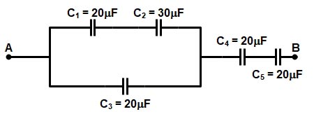
Ques.6. What is the equivalent capacitance (in μF) for the circuit given below?
4.56
7.5✓
54.56
54.28
In the given circuit the capacitance C1 and C2 are parallel with the capacitance C3 i.e
(C1 || C2) + C3
∴(20 × 30) ⁄ (20 + 30) + 20
CA= 12 + 20 = 32 μF
Now capacitance CA, C4, & C5 are in the series therefore
Ceqv = (1/30 + 1/20 + 1/20)
Ceqv = (60/8) = 7.5 μF
Ques.7. What will be the resistance (in ohms) of a lamp rated at 220 V, 200 W?
220
224
244
242✓
The power can be defined as
P = V2 ⁄ R
Given
P = 200 W
V = 220 V
200 = 2202 ⁄ R
R = 242 Ω
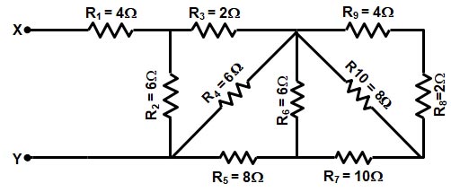
Ques.8. What will be the equivalent resistance (in Ω) for the circuit given below?
5
7✓
10
4
In the given circuit the resistance R9 and R8 are Parallel with Resistance R10 therefore
(R9 + R8) || R10
= {(4 + 2) × 12} ⁄ {(4 + 2) + 12}
= (6 × 12) ⁄ (6 + 12)
RA = 4Ω
Now resistance RA and R7 is parallel with Resistance R6
∴ {(4 + 8) × 6} ⁄ {(4 + 8) + 6}
= (12 × 6) ⁄ (12 + 6)
RB = 4Ω
Now the circuit becomes as shown in the figure
Resistance RB and R7 is parallel with Resistance R4
{(4 + 8) × 6} ⁄ {(4 + 8) + 6}
= (12 × 6) ⁄ (12 + 6)
RC = 4Ω
Now resistance RC and R3 is parallel with Resistance R2
{(4 + 2) × 6} ⁄ {(4 + 2) + 6}
RD = 3
Now our final circuit becomes as shown in the figure
Therefore the equivalent resistance is
R1 + RD
Req = 4 + 3 = 7Ω
Ques.9. Two wires of the same resistivity have equal length. The cross-sectional area of first wire is two times to the area of the other. What will be the resistance (in ohms) of the wire that has a large cross-sectional area, if the resistance of the other wire is 20 Ohms?
40
20
30
10✓
The resistance of the conductor is determined by the
R = ρL/A
Let the resistance of the wire 1 be R1 and the resistance of the wire 2 is R2
The wire has the same length and resistivity therefore
The resistance of the conductor is determined by the
ρ1 = ρ2
&
L1 = L2
Now the cross-sectional area of the first wire is 2 times the second wire