
Ques.91. The type of circuit that does not need a coupling capacitor is
- Resistance Loaded
- Transformer coupled✓
- Impedance coupled
- Single-tuned
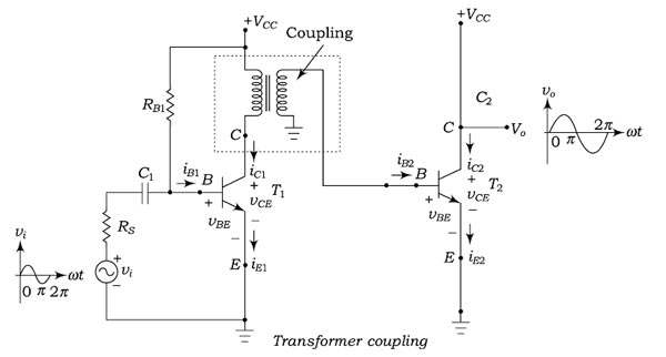
Function of the coupling capacitor In most of the practical cases, you will not see a single amplifier. Rather than you will see a series of the cascaded amplifier. The term cascaded means connected in series. Coupling capacitors are commonly used to connect one amplifier stage to another. In analog circuits, a coupling capacitor is used to connect two circuits such that only the AC signal from the first circuit can pass through to the next while DC is blocked. This technique helps to isolate the DC bias settings of the two coupled circuits. Capacitive coupling is also known as AC coupling and the capacitor used for the purpose is also known as a DC-blocking capacitor. Transformer coupling The Transformer coupling is shown in Fig and is mostly employed for impedance matching. In general. the last stage of the multistage amplifier is the power stage. This stage delivers the maximum power to the load e.g. a loudspeaker. For maximum power transfer, the impedance of the power source must be equal to that of the load. In this scheme, the primary winding of the transformer is used as a collector load and the secondary winding of the transformer transmits the ac output voltage signal directly to the base of the next-stage amplifier. Hence there is no requirement for coupling capacitors. Moreover, the secondary winding also provides a base return path, and there is no need for base resistance. Amplifiers using this coupling are called transformer-coupled.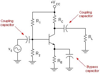
Ques.92. The plate current in a triode can be controlled by controlling
- Plate voltage
- Grid voltage✓
- Plate voltage and grid voltage
- Grid current
The vacuum diode is used to convert the alternate current into the direct current. However, they can not increase or amplify the electrical signal. In other words, they can not increase the voltage or power. To increase the electrical signal, an additional electrode is required. When the extra electrodes are placed between the cathode and anode, the resulting electronic device is called the vacuum triode. The construction of triodes is similar to that of vacuum diode with the different diet vacuum triode consists of one extra electrode as compared to vacuum diode. The three electrodes of the vacuum triode are anode or plate, cathode, and control grid. The cathode is also called an emitter because they emit free electron when heated. Cathode emits the electrons by the thermionic process. The function of the anode is to collect the free electrons that are emitted by the cathode. Hence, anode or plate is also called the collector. If the plate is at a positive potential with respect to the cathode, electrons move towards the plate through the openings of the control grid. The control grid is present between the anode and cathode. The control grid is placed near the cathode surface to control the plate current more efficiently. By applying proper voltage on the control grid we can vary plate current. In a triode, the control grid is used to vary plate current. The control grid is in form of a fine mesh, which allows electrons to pass through it. But control grid can vary the plate current in a better way than plate voltage. Hence, in the case of a triode, we can vary plate current by varying voltage either on the plate or on the control grid. Therefore the control grid is also called an electric current controller or electron controller. The control grid is made of a network of wires that controls the electron’s flow between the cathode and anode. The space between the network of wires in the grid is very large. Hence, the free electrons move easily from cathode to anode through the opening of the control grid. Free electrons that are moving from cathode to anode will carry the electric current. Change in potential exerted by the grid is much greater than that exerted by the plate, i.e., a very small change in grid potential produces a large change in plate current. (Thi property makes use of triode as an amplifier.)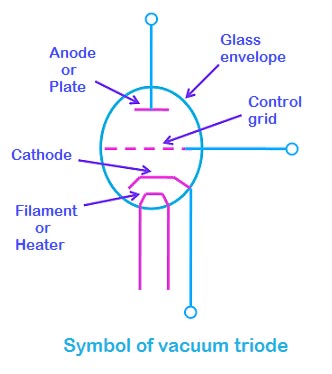
Ques.93. A transistor consists of
- One P-N Junction
- Two P-N Junction✓
- Three P-N junction
- Four P-N junction
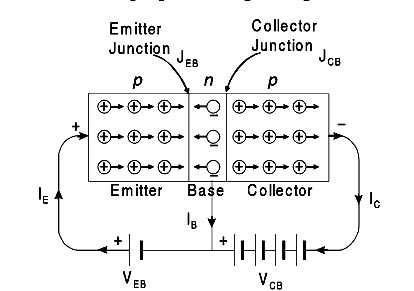
In reality, a transistor is the solid-state version of a vacuum triode, which was initially known as a semiconductor triode. The terminology transistor is attributed to John R Pierce. A Bipolar Junction Transistor (BJT) is a three-layer, two junction semiconductor device consisting of either two N-type and one P-type layer of material (NPN transistor) or two P-type and one N-type layer of material (PNP transistor). If a thin layer of N-type Silicon is sandwiched between two layers of P-type silicon. This transistor is referred to as PNP. Alternatively, in an NPN transistor, a layer of P-type material is sandwiched between two layers of N-type material. The term bipolar is to justify the fact that holes and electrons participate in the injection process into the oppositely polarised material. If only one carrier is employed (electron or hole). it is considered a unipolar device. A transistor thus transfers a weak signal from low resistance to high resistance.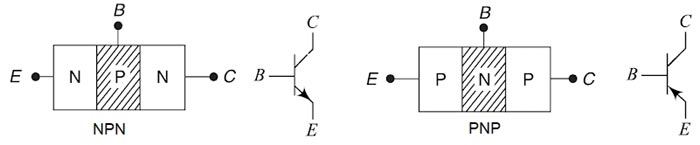
Ques.94. The CE amplifier is most commonly used because of
- Less Power gain
- Less Output Voltage
- More Power Gain✓
- Low Cost
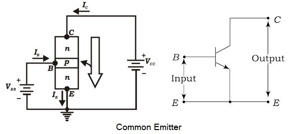
In CE amplifier circuit the emitter terminal is common to both the input i. e. base-emitter circuit and the output i.e. the collector-emitter circuit and is grounded. The input (or emitter) circuit is forward biased by connecting the positive of the emitter-base battery VBB to the emitter terminal and the output (or collector) circuit is reverse biased by connecting the negative of the collector-emitter battery VCC to the collector terminal. So, output resistance is more than input resistance. Out of the three transistor connections, the common-emitter circuit is the most efficient. It is used in about 90 to 95 percent of all-transistor applications. The main reasons for this are : In a common emitter connection, Ic is the output current and IB is the input current. The collector current here is expressed as: Ic = βIB + ICEO As the value of β is very large, therefore, the output current IC is much more than the input current IB. This increases the current gain effectively. The current gain of CE arrangement ranges from 20 to High Voltage and Power Gain As we have seen above, CE arrangement has a high current gain. This in turn, increases the voltage and power gain of the CE circuit. In comparison to CB and CC circuits, the common emitter connection has the highest voltage and power gain. For this reason, the CE transistor connection is often used for amplifying purposes. [ninja_tables id=27501]
Where β = Current Gain
ICEO = Collector-Emitter current
500.
Ques.95. Synchronous Motor Shaft is Made of
- Alnico
- Chrome Steel
- Mild Steel✓
- Stainless Steel
A shaft is a rotating machine element, usually circular in cross-section, which is used to transmit power from a machine to a machine that absorbs power. Low carbon steel which is also called mild steel (MS) is an alloy of iron and carbon. The carbon content varies from 0.05 to 0.15 percent for dead mild steel and 0.15 to 0.3 percent for mild steel. The shaft is generally made of mild steel When high strength is required, alloy steel such as nickel, nickel-chromium or chromium-vanadium steel is used. Mechanical power is taken or given to the machine through the shaft.
Ques.96. When the voltage applied to a synchronous motor is increased, which of the following will reduce?
- Stator Flux
- Pull-in Torque
- Pull out Torque
- None of these✓
Let us know the factors, facts, assumptions that are dependent on supply voltage for good operation of the synchronous motor. The synchronous motor is a dual-excited constant speed motor, Basically supply voltage is injected such that it produces RMF at specified phase angles wrt to phases in the stator of our motor. As in the case of Induction motors Variation in the frequency of the source will result in the corresponding change in the flux in the air gap. Hence, in order to operate the motor with the fairly constant flux in the air gap, it is necessary to vary the magnitude of the applied voltage in the same ratio as the frequency of the supply (i.e V/f should be kept constant) and to keep the excitation current constant. If a synchronous motor is driven by an external power source, and the excitation, or voltage applied to the rotor, is adjusted to a certain value called 100 percent excitation, no current will flow from or to the stator winding. In this case, the voltage generated in the stator windings by the rotor, or back EMF, exactly balances the applied voltage. However, if the excitation is reduced below the 100-percent value, the difference between the back emf and the applied voltage produces a reactive component of current which lags the applied voltage. The machine then acts as an inductance. Similarly, if the excitation is increased above the 100-percent value, the reactive component leads the applied voltage, and the machine acts as a capacitor. This feature of the synchronous motor permits the uses of the machine as a power-factor correction device. When so used, it is called the synchronous condenser. Note:- In most applications, the voltage applied to the synchronous machine cannot be varied. This is true because in most cases the machine is directly connected to the grid and the terminal voltage is therefore fixed.
RMF produces enough constant magnitude flux, Let us assume that initially our synchronous motor was operated at a voltage less than the preset voltage value.
Ques.97. A synchronous motor has better power factor than an induction motor. This is due to
- Stator supply is not required to produce the magnetic field✓
- Synchronous Motor has no Slip
- Mechanical Load on the rotor remain constant
- Synchronous motor has the large airgap
A synchronous motor is a machine that converts electric power into mechanical power at a constant speed called synchronous speed. It is a doubly excited machine because its rotor winding is excited by direct current and its stator winding is connected to an A.C supply. Stator: The stator is the stationary part of the machine. The three-phase armature winding is placed in the slots of the stator core and is wound for the same number of poles as the rotor. The stator is excited by a three-phase ac supply as shown in the Figure Rotor: The rotor of synchronous motor can be of the salient pole or cylindrical pole (Non-salient) type construction. Practically most of the synchronous motor use salient i.e., projected pole type construction, except for exceedingly high-speed machines. The field winding is placed on the rotor and it is excited by a separate dc supply. Although the synchronous motor starts as an induction motor. it does not operate as one. After the armature winding has been used to accelerate the rotor to about 95% of the speed of the rotating magnetic field, direct current is connected to the rotor and the electromagnets lock in step with the rotating field. Notice that the synchronous motor does not depend on the induced voltage from the stator field to produce a magnetic field in the rotor. The magnet field of the rotor is produced by external DC applied to the rotor. This is the reason that the synchronous motor has the ability to operate at the speed of the rotating magnetic field. As the load is added to the motor, the magnetic field of the rotor remains locked with the rotating magnetic field and the rotor continues to tuna at the same speed. It should be noted that the changes in the dc field excitation do not affect the motor speed. However, such changes do alter the power factor of a synchronous motor. If all of the resistance of the rheostat is inserted in the field circuit, the field current drops below its normal value. A poor lagging power factor results. If the dc field is weak, the three-phase ac circuit to the stator supplies a magnetizing current to strengthen the field. This magnetizing component lags the voltage by 90 electrical degrees. The magnetizing current becomes a large part of the total current input. This gives rise to a low lagging power factor. If a weak dc field is strengthened, the three-phase ac circuit to the stator supplies less magnetizing current. Because this current component becomes a smaller part of the total current input to the stator winding, the power factor increases. The field strength can be increased until the power factor is unity or 100%. When the power factor reaches unity, the three-phase ac circuit supplies energy current only. The dc field circuit supplies all of the current required to magnetize the motor. The amount of dc field excitation required to obtain a unity power factor is called normal field excitation. The magnetic field of the rotor can be strengthened still more by increasing the dc field current above the normal excitation value. The power factor in this case decreases. The circuit feeding the stator winding delivers a demagnetizing component of current. This current opposes the rotor field and weakens it until it returns to the normal magnetic strength. Hence Higher PF means the low requirement of MMF for energy transfer, hence low magnetizing current requirement. The synchronous machine has separate DC excitation which reduces the machine’s excitation dependency on the main supply, hence better PF. whereas the Induction motor has no such provisions, hence low Power factor.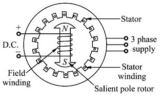
Ques.98. When the field circuit of an unloaded salient pole synchronous motor gets suddenly open circuited then?
- The Motor Stops✓
- It runs at a slower speed
- It continues to run at the same speed
- It runs at a very high speed
The synchronous motor either run at synchronous speed or it will not run at all. The synchronous motor starts as an induction motor. it does not operate as one. After the armature winding has been used to accelerate the rotor to about 95% of the speed of the rotating magnetic field, direct current is connected to the rotor and the electromagnets lock in step with the rotating field. Notice that the synchronous motor does not depend on the induced voltage from the stator field to produce a magnetic field in the rotor. The magnet field of the rotor is produced by external DC applied to the rotor. To shut down the motor, the field circuit is de-energized by opening the field discharge switch. The field discharge resistor is connected across the field circuit to reduce the induced voltage in the field as the field flux collapses. The energy stored in the magnetic field is spent in the resistor, and a lower voltage is induced in the field circuit thus rotating the magnetic field will not develop and the motor will stop. Note:- The synchronous motor either run at synchronous speed or it will not run at all.
Ques.99. The armature current of a synchronous motor is minimum when operating at
- Unity Power factor✓
- 0.707 Power factor lagging
- 0.707 power factor leading
- Zero power factor leading
The power factor of the synchronous motor can be changed by changing the field current. When the field current is changed, the armature current of the synchronous motor also changes. Now suppose that a synchronous motor is running at no load. If the field current is increased, the armature current la decreases until the armature current becomes the minimum. At this point, the synchronous motor is running at the unity power factor. Before this point, the synchronous motor was running at the lagging power factor and the armature current is low lagging. Now if we increase the field current, the armature current increases (high Lagging) and the motor starts operating at a leading power factor. It must be noted that due to the constant load, the cosine component of the armature current, In cosφ always remains constant. The V-curves of a synchronous motor show how armature current varies with its field current when the motor input is kept constant and is so-called because of their shape. Minimum armature current corresponds to unity power factor.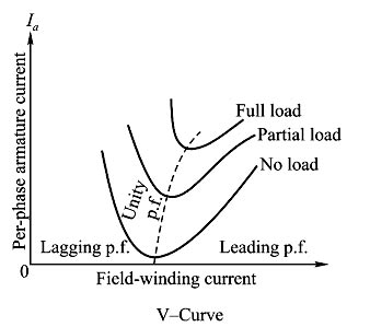
Ques.100. The resultant armature voltage of a synchronous motor is equal to the _______.
- Vector sum of Eb and V
- Vector difference of Eb and V✓
- Arithmetic sum of Eb and V
- Arithmetic difference between Eb and V
The resultant armature voltage of a synchronous motor is equal to the vector difference of Eb and V. When a dc motor or an induction motor is loaded, the speed of the motor drops. This is because the load torque demand increases more than the torque produced by the motor. Hence the motor draws more current to produces more torque to satisfy the load but its speed reduces. In case of synchronous motor speed always remains constant equal to the synchronous speed, irrespective of load condition It is interesting to study how synchronous motor reacts to changes in the load condition. In a dc motor, armature develops an emf after motoring action starts which opposes the supply voltage called back emf. Eb. The resultant voltage across the armature is (V – Eb) and it causes an armature current la = (V – Eb) ⁄ Ra to flow where Ra is armature circuit resistance. In case of the synchronous motor also, once the rotor starts rotating at synchronous speed, the stationary stator (armature) conductors cut the flux produced by the rotor. The only difference is the conductor is stationary and flux is rotating. Due to this, there is an induced emf in the stator which according to Lenz’s law opposes the supply voltage. This induced emf is called back emf in case of the synchronous motor. It is denoted as Ebph i.e., back emf per phase. This gets generated as the principle of the alternator and hence alternating in nature. So back emf in case of the synchronous motor depends on the excitation given to the field winding and not on the speed as speed is always constant. The net voltage in armature (stator) is the vector difference (not arithmetical, as in d.c. motors) of Vph and Ebph. Armature current is obtained by dividing this vector difference of voltages by armature impedance (not resistance as in d.c. machines).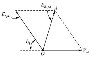
For SSC JE 2018 SET-1 Electrical paper with complete solution Click Here
For SSC JE 2018 SET-2 Electrical paper with complete solution Click Here
For SSC JE 2018 SET-3 Electrical paper with complete solution Click Here
For SSC JE 2017 Electrical paper with complete solution Click Here
For SSC JE 2015 Electrical paper with complete solution Click Here
For SSC JE 2014 (Evening shift) Electrical paper with complete solution Click Here
For SSC JE 2014 (Morning shift) Electrical paper with complete solution Click Here
For SSC JE 2013 Electrical paper with complete solution Click Here
For SSC JE 2012 Electrical paper with complete solution Click Here
For SSC JE 2011 Electrical paper with complete solution Click Here
For SSC JE 2010 Electrical paper with complete solution Click Here
For SSC JE 2009 Electrical paper with complete solution Click Here


