Ques.11. Which of the following statement is CORRECT?
Superposition theorem is applicable to only those circuits that only have active elements.
Superposition theorem is applicable to only those circuits that only have passive elements.
Superposition theorem is applicable to only those circuits that only have linear bilateral elements.✓
Superposition theorem is applicable to only those circuits that only have non-linear bilateral elements.
Linear circuit:- A linear circuit is an electric circuit in which circuit parameters (Resistance, inductance, capacitance, waveform, frequency, etc) are constant. In other words, a circuit whose parameters are not changed with respect to Current and Voltage is called Linear Circuit.
Bilateral Circuit:- A circuit Whose characteristics are the same in either direction of the current flow is called a bilateral circuit. The electrical transmission line is an example of the bilateral circuit as it performs its functions equally Bell in both directions. Whereas, a diode is a unilateral element, unlike a bilateral element in which the direction of flow of current affects circuit behavior. In forward bias, it has the least resistance and allows maximum current through it. In reverse bias, it offers high resistance to the flow of current.
Superposition Theorem
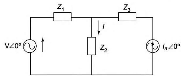
An electrical circuit may contain more than one source of supply. The sources of supply may be a voltage source or a current source. In solving circuit problems having multiple sources of supply, the effect of each source is calculated separately and the combined effect of all the sources is taken into consideration. This is the essence of the superposition theorem.
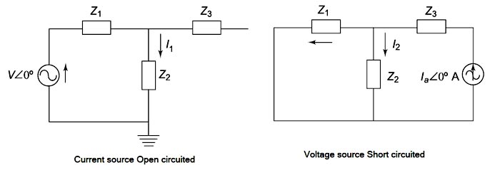
The superposition theorem states that in a linear bilateral network containing more than one source, the current flowing in any branch is the algebraic sum of currents that would have been produced by each source taken separately, with all the other sources replaced by their respective internal resistances. In case the internal resistance of a source is not provided, the Voltage sources will be short-circuited and the current source is open-circuited.
This theorem is called superposition because we superpose or algebraically add the components (currents or voltages) due to each independent source acting alone to obtain the total current in or voltage across a circuit element.
Ques.12. The algebraic sum of all the voltages around any closed path is
Negative
Zero✓
One
Infinite
Kirchhoff’s Voltage Law (KVL,) or Kirchhoff’s Loop Rule. This law is based on the conservation of energy and maybe stated as under:
In any closed electrical circuit or loop, the algebraic sum of all the electromotive force (e.m.f s) and voltage drops in resistors is equal to zero, i.e., in any closed circuit or loop.
The algebraic sum of e.m.f s + Algebraic sum of the voltage drops = 0
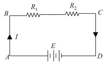
The validity of Kirchhoff’s voltage law can be easily established by referring to the loop ABCDA shown in Fig.
If we start from any point (say point A) in this closed circuit and go back to this point (i.e., point A) after going around the circuit, then there is no increase or decrease in potential.
This means that the algebraic sum of the e.m.f.s of all the sources (here only one e.m.f. source is considered) met on the way plus the algebraic sum of the voltage drops in the resistances must be zero. Kirchhoff’s voltage law is based on the law of conservation of energy, i.e., the net change in the energy of a charge alter completing the closed path is zero.
V1 + V2 − V = 0
or
Kirchhoff’s voltage law is also called as loop rule.
Ques.13. Which one of the following law is based on the principle of conservation of electric charge?
Kirchhoff’s Current Law✓
Kirchhoff’s Voltage Law
Ohm’s Law
Coulomb’s Law
Kirchhoff’s Current Law (KCI ) or Kirchhoff’s Junction Rule. This law is based on the conservation of charge and may be stated as under:
The algebraic sum of the currents meeting at a junction in an electrical circuit is zero.
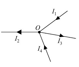
An algebraic sum is one in which the sign of the quantity is taken into account. For example, consider four conductors carrying currents I1, I2, I3, & I4 and meeting at point O as shown in Fig
If we take the signs of currents flowing towards point O as positive, then currents flowing away from point O will be assigned a negative sign. Thus, applying Kirchhoff’s current law to the junction O we have,
i.e., Sum of incoming currents = Sum of outgoing currents.
Therefore, Kirchhoff’s current law may also be stated as under:
The sum of currents flowing towards any junction in an electrical circuit is equal to the sum of currents flowing away from that junction. Kirchhoff’s current law is rightly called the junction rule.
Kirchhoff’s current law is true because electric current is merely the flow of free electrons and they cannot accumulate at any point in the circuit. This is in accordance with the law of conservation of charge. Hence, Kirchhoff’s current law is based on the law of conservation of charge.
Ques.14. The source resistance of an ideal voltage source should be
Infinite
One
Zero✓
Greater than one
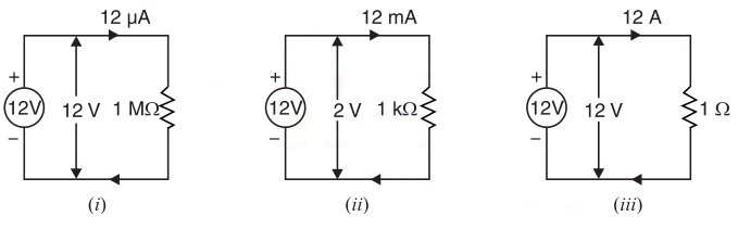
An ideal voltage source is a two-terminal device whose terminal voltage is independent of the current drawn by the network connected to its terminals.
Both the magnitude and wave corn of voltage remain unaffected. This means an ideal voltage source should have zero internal resistance of source resistance. Therefore, it would provide constant terminal voltage regardless of the value of the load connected across its terminals.
For example, an ideal 12V source would maintain 12V across its terminals when a 1 MΩ resistor is connected (so I = 12 V/1 MΩ = 12μA) as well as when a 1 kΩ resistor is connected ( I = 12 mA) or when a 1 Ω resistor is connected (I = 12A).
Ques.15. What will be the voltage across Resistance R2 in the circuit given below?
14.35
13.33✓
15.45
12.33
The voltage across the resistance R2 can find out by the voltage divider rule.
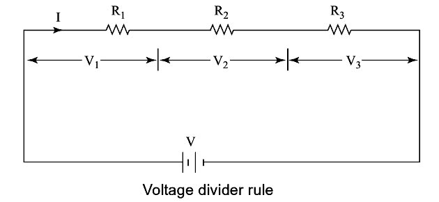
Voltage Divider Rule (VDR)
The voltage divider rule provides a useful formula to determine the voltage across any resistor when two or more resistors are connected in series with a voltage source. The voltage across the individual resistors can be given in terms of the supply voltage and the magnitude of individual resistances as follows
I = V ⁄ (R1 + R2 + R3)
V1 = I.R1 = V.R1 ⁄ (R1 + R2 + R3)
Similarly
V2 = I.R2 = V.R2 ⁄ (R1 + R2 + R3)
Hence for the given question the voltage across the resistance R2
V2 = V.R2 ⁄ (R1 + R2)
V2 = 20 × 40 ⁄ (20 + 40)
V2 = 13.33 Volt
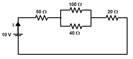
Ques.16. What will be the value of the current (in mA) for the given electrical circuit?
0.11
110
0.101
101✓
In the above circuit, the resistance of 100 Ω and 40 Ω are in parallel
R = (100 × 40) ⁄ (100 + 40)
R = 28.57 Ω
Now all the three resistance 50 Ω, 28.57Ω, 20Ω are in series with each other
R = 98.57 Ω
Now the current in the circuit
I = V/R = 10/98.57
I = 0.101 A = 0.101 mA
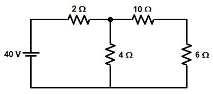
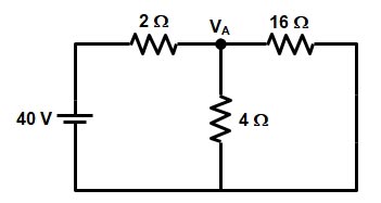
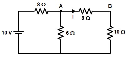
Ques.17. What will be the value of current (in A) through the 6Ω resistor for the given circuit diagram?
5.45
5.89
1.54✓
7.69
The resistance 10Ω and 6Ω are in series with each other
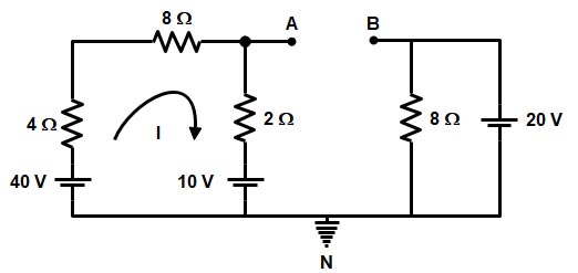
Ques.18. Determine the Thevenin’s voltage (in V) and Thevenin’s resistance (in Ω) across the 6Ω resistor for the given electrical circuit respectively
5.72, 1.71✓
4.67, 2.24
3.54, 1.01
4.87, 2.09
Thevenin’s Voltage
To find Thevenin’s voltage remove the Load resistance i.e 6Ω from the circuit as shown in the figure and potential at point N to be zero.
Now applying the Kirchhoff law in loop 1 we get
40 − 4I − 8I − 2I − 10 = 0
14I =30
I = 2.14 A
Hence the voltage drop across 2Ω resistance will be
10 + 2 × 2.14 = 14.28 V
In the second Loop the resistance, 8Ω is connected across the 20 V hence the voltage drop will be also equal to 20 V
Hence the potential at points A and B is 14.28 V and 20 V respectively
Since “B” is at the high potential, therefore, the Thevenin’s Voltage
VTH = VB − VA
VTH = 20 − 14.28 = 5.72 Volt
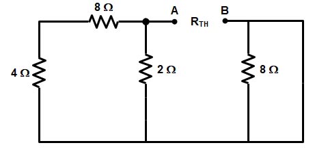
Thevenin’s Resistance
Now to Find Thevenin’s Resistance RTH replace all the voltage sources with the short circuit as shown in the figure
Since the 8 Ω resistance from the second loop is short-circuited and can be ignored Hence Thevenin’s Equivalent resistance will be
RTH = (8 + 4) || 2
= (12 × 2) ⁄ (12 + 2)
RTH = 24 ⁄ 14 = 1.71 Ω
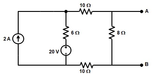
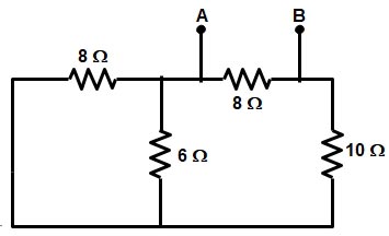
Ques.19. What will be the value of Norton’s resistance (in Ω) between terminals A and B for the circuit given below?
5.65
6.11✓
4.32
7.45
To find the Norton Resistance Rth, the voltage source is replaced by its internal resistance and the current source is replaced by the open-circuits as shown in the figure
Rth = (10 + 6 + 10) || 8
Rth = 26 || 8
Rth = (26 × 8) ⁄ (26 + 8)
Rth = 6.11 Ω
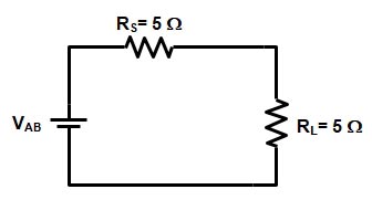
Ques.20. Find the maximum power (in W) transfer from the source to the load for the circuit diagram given below
0.25
0.32
0.13✓
0.42
Equivalent Voltage
We will apply Thevenin’s theorem to reduce the circuit into a single voltage source connected across the load terminals A and B as shown in the figure.
Now We will find the Thevenin’s Voltage by applying the nodal analysis