
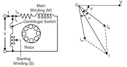
Ques.61. A centrifugal switch is provided for disconnecting the auxiliary winding in a
- Capacitor start Motor✓
- Capacitor Run Motor
- Reluctance motor
- Hysteresis Motor
The centrifugal switch is used to disconnect the start winding from the circuit when the motor reaches approximately 75% of the rated speed. A centrifugal switch is a mechanical device attached to the end of the shaft with weights that will sling outward when the motor reaches approximately 75% speed. For example, if the motor has a rated speed of 1725 rpm, the centrifugal weights will change position at 1294 r.p.m (1725 x 0.75) and open a switch to remove the start winding from the circuit. This switch is under a fairly large current load, so a spark will occur. If the switch fails to open its contacts and remove the start winding, the motor will draw too much current, and the overload device will cause it to stop. When the motor is de-energized, it will slow down and the centrifugal switch will close its contacts in preparation for the next motor starting attempt. The more the switch is used, the more its contacts will burn from the arc. If this type of motor is started many times, the first thing that will likely fail is the centrifugal switch. This switch makes an audible sound when the motor starts and stops. Hence if the starting switch fails to open when needed, the starting winding mill almost always overheats and burns out. Note:- Centrifigual switch is not used in reluctance motor and hysteresis Motor.
Ques.62. In a split-phase motor, the running winding should have
- High resistance and low inductance
- Low resistance and high inductance✓
- High resistance as well as high inductance
- Low resistance as well as low inductance
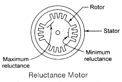
Ques.63. A reluctance motor
- Self-Starting Motor
- Constant Speed Motor
- Need no-dc excitation
- All of the above✓
It is a single-phase synchronous motor that does not require d.c. excitation to the rotor. Its operation is based upon the following principle: Whenever a piece of ferromagnetic material is located in a magnetic field, a force is exerted on the material, tending to align the material so that reluctance of the magnetic path that passes through the material is minimized. Working Principle The stator consists of a single winding called the main winding. But single winding cannot produce a rotating magnetic field. So for the production of a rotating magnetic field, the must be at least two windings separated by a certain phase angle. Hence stator consists of an additional winding called auxiliary winding which consists of the capacitor in series with it. Thus there exists a phase difference between the currents carried by the two winding and corresponding fluxes. Such two fluxes react to produce the rotating magnetic field. The technique is called the split-phase technique of the production of a rotating magnetic field. The speed of this field is the synchronous speed which is decided by the number of poles for which stator winding is wound. The rotor carries the short-circuited copper or aluminum bars and acts as a squirrel cage rotor of an induction motor. If an iron piece is placed in a magnetic field, it aligns itself in a minimum reluctance position and gets locked magnetically. Similarly, in the reluctance motor, the rotor tries to align itself with the axis of the rotating magnetic field in a minimum reluctance position. But due to rotor inertia, it is not possible when the rotor is at standstill. So rotor starts rotating near synchronous speed as a squirrel cage induction motor. When the rotor speed is about synchronous, the stator magnetic field pulls the rotor into synchronism i.e. minimum reluctance position and keeps it magnetically locked. Then the rotor continues to rotate with a speed equal to synchronous speed. Such a torque exerted on the rotor is called the reluctance torque. Thus finally the reluctance motor runs as a synchronous motor. The resistance of the rotor must be very small and the combined inertia of the rotor and the load should be small to run the motor as a synchronous motor. Advantages The reluctance motor has the following advantages Limitations The reluctance motor has the following limitationReluctance Motor
Ques.64. The speed control of a universal motor used for sewing machines is done by
- Friction
- Varying the resistance✓
- Tapping the field
- Centrifugal Mechanism
The universal motor is one that operates both on A.C and D.C supply. Its principle of operation is the same as that of a de series motor, i.e., force is created on the armature conductors due to the interaction between the main field flux and the flux created by the current-carrying armature conductors. Since the universal motor is a series-wound, it has performance characteristics similar to a In a universal motor, the third set of coils called compensating windings is connected in series with the rotor and stator. These windings perform two functions: They correct the neutral plane position that is distorted by armature reaction, and they compensate for undesirable reactive voltages attributed to the inductance of the armature. The speed of a universal motor is determined by the following factors: Universal motors are speed-regulated by inserting resistance in series with the motor. The resistance may be tapped resistors, rheostats, or tapped nichrome with coils wound over a single field pole. The resistance is connected before the motor, therefore the current to the motor is reduced, which in turn reduces the speed of the motor according to the setting of that variable resistance. An application example is a sewing machine. Its speed is varied by a foot pedal, Chicle contains a variable resistor. Another example is a variable-speed hand drill. As the trigger is pulled, resistance in series with the motor is changed to vary the RPM. By tapping a field coil at various points, as shown in Figure, different inductive reactance values are developed. When the switch is set at the low-speed position, the entire winding is used and the maximum inductive reactance forms and causes minimum current to flow. At the high-speed position setting, the entire coil is bypassed and the inductive reactance is reduced, causing a higher current to flow. An application example of this principle is a blender. A different field pole connection is made for each speed position setting.
Resistance Method for Speed control of Universal Motor
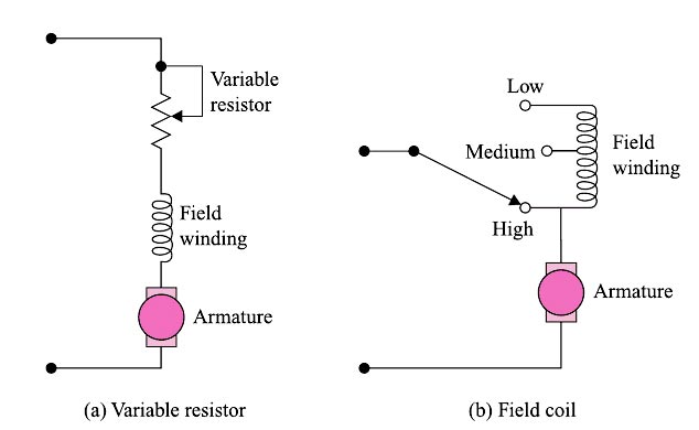
Field Tapping Method of speed control of universal motor
Ques.65. The power factor of a single-phase induction motor is usually
- Lagging✓
- Always Leading
- Unity
- Unity to 0.8 leading
The induction motor, of course, takes electrical power and converts most of it to mechanical shaft power; and, when it does, it absorbs the electrical power. Here the current always lags the voltage or is said to have a lagging power factor.
Ques.66. Hysteresis motors are suitable for
- Fans
- Blowers
- Sound equipment✓
- Mixer Grinder
The hysteresis motor can be considered as a self-starting synchronous motor. From the time of starting until it reaches synchronous speed, the motor produces a synchronizing torque and an ideally flat speed/torque characteristic. Due to the absence of slots and teeth on the rotor, the operation of this motor is smooth and quiet as there is no mechanical vibration. The motor behavior is similar to that of a conventional synchronous motor but there is no excitation winding on the rotor or permanent magnets, giving the motor a high efficiency and power factor. These characteristics make it ideal for many industrial applications, such as in electronic and medical equipment, tape and video recorder drives, computer drives, clocks, gyroscope rotors for inertial navigation, robotics, and other special applications where precision and reliability are required.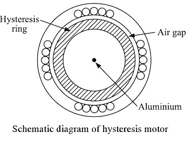
Ques.67. A relay used on short transmission lines is
- Reactance Relay✓
- Mho’s Relay
- Impedance Relay
- None of these
Note:- In the case of short lines, power surges remain for a shorter period, and hence, their effect is unimportant. The predominant factor is, therefore, the effect of arc resistance. The effect of power surges stays for a longer period in the case of long lines and hence, a relay that is least affected by power surges is preferred for the protection of long lines. The MHO unit is less affected by power surges than the impedance and reactance relays and hence, it is best suited for the protection of long lines against phase
Ques.68. The highest voltage transmission line starting from generating point is called
- Secondary transmission
- Secondary distribution
- Primary transmission✓
- Primary Distribution
Electric power transmission, a process for the delivery of electricity to consumers, is the bulk transfer of electrical power. All major generating stations are usually interconnected by transmission lines or network that distributes the power from generating stations to the distribution systems, which ultimately supply the load points or load centers. Primary transmission: The generated electric power (in 132, 220, 500 kV, or greater) is transmitted to load points by the three-phase three-wire overhead transmission system. This type of transmission is called primary transmission, which is also known as extra-high-voltage AC (EHV-AC) transmission. Primary transmission is generally done through overhead transmission lines. The high voltage overhead lines are generally constructed by the aluminum alloy made up of several strands and reinforced with steel strands. The primary transmission uses a three-phase three-wire system. Secondary transmission: The primary transmission ends at a substation known as Receiving Station (RS), which is far from the city (outskirts). At receiving station, the level of voltage is reduced by step-down transformers up to 132, 66, or 33 kV, and electric power is transmitted by the three-phase three-wire overhead system to different substations located in the city. It is known as secondary transmission. The power is transmitted to various stations using the overhead 3-phase 3 -wire System. The conductor, used for the secondary transmission are called feeders. Distribution System:- At the substations, transformers are again used to step the voltage down to a lower voltage for distribution to commercial and residential users. This distribution is accomplished with a combination of sub-transmission (33 kV to 115 kV, varying by country and customer requirements) and distribution (3.3 to 25 kV). Finally, at the point of use, the energy is transformed to low voltage with the help of step-down transformers (100 to 600 V, varying by country and customer requirements). Similar to the transmission, the distribution of electric power is also divided broadly into two parts: (i) Primary Distribution: At the substations, the voltage level is reduced to 6.6 kV, 3.3 kV, and 1.1 kV with the help of a step-down transformer. It uses the 3-phase 3-wire underground system. And the power is further transmitted to the local distribution centers. This primary distribution is also called High Voltage (HV) Distribution. For larger consumer-like factories and industries, the power is directly transmitted to such loads from a substation. Such big loads have their own substations. (ii) Secondary Distribution: At local distribution centers, the voltage level of 6.6 kV, 1.1 kV is further reduced to 440 V using distribution transformers. The power is then transmitted to the user or consumers; this is called a secondary distribution. The 1-phase lightening loads are supplied using a line and neutral wire. Loads like three-phase motors are supplied using the three-phase line
Ques.69. A 30 km transmission line carrying power at 33 kV is known as
- Short Transmission line✓
- Long Transmission line
- Medium transmission line
- Ultra high voltage line
Transmission lines are classified into three types based on the length of the transmission line and the operating voltage. They are: Short transmission lines:- When the length of an overhead transmission line is about 50 km with an operating voltage upto 20 kV, it is considered as the short transmission line. Due to the smaller length and low operating voltage, the charging current is low. So, the effect of capacitance on the performance of short transmission lines is extremely small and therefore, can be neglected. Thus only resistance and inductance is to be taken into account while analyzing short transmission lines. Medium transmission lines:- When the length of the transmission line is lying between 50 to 150 km and the line voltage is moderately high i.e. in between 20 kV and 100 kV, it is treated as the medium transmission line. In the analysis of the medium transmission line, the capacitance is taken into account as the line length is appreciable. Long transmission line: When the length of the transmission line is more than 150 km and the line voltage is very high i.e. above 100 kV, the line is considered a long transmission line. In the analysis of such lines, the line constants are considered uniformly distributed over the whole length of the line.
Ques.70. The insulating material for cables should be
- Non-hygroscopic
- Non-inflammable
- Acid proof
- All options are correct✓
Cables are used for the transmission and distribution of electrical energy in highly populated areas of towns and cities. Cables from the artery system for the transmission and distribution of electrical energy. A cable is basically an insulated conductor. External protection against mechanical injury, moisture entry, and chemical reaction is provided on the cable. The conductor is usually aluminum or annealed copper, while the insulation is mostly polyvinyl chloride (PVC) or other chemical compounds. The transmission line is more expensive than overhead lines, especially at high potentials. Besides the increase in temperature is high in the cables. However, there is the limitation of raising the operating voltage. In low and medium voltage distribution in urban areas, cables are more widespread. In generals a cable must fulfill the following necessary requirements:


