
Ques.51. Which of the following generators are used in arc welding
- Shunt generators
- Series Generator
- Cumulative compound generators
- Differential compound generators✓
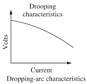
Arc welding is the widely used method of joining metal parts. Here the source of heat is an electric arc. Arc welding is a group of welding processes wherein heating is produced with an electric arc or arcs, mostly without the application of pressure and with or without the use of fillet metal, depending upon the base plate thickness. ARC Welding Principle In arc welding, the ARC is generated between the positive pole of D.C. (direct current) called the anode and the negative pole of D.C. called the cathode. When these two poles are brought together, and separated for a small distance (1.5 to 3 mm) such that the current continues to flow through a path of ionized particles, called plasma, an electric arc is formed. Since the resistance of this ionized gas column is high, so more ions will flow from the anode to the cathode. Heat is generated as the ions strike the cathode. A.C. or D.C. Machines in ARC Welding Depending upon the application, A.C. or D.C. machines are used in arc welding, but in some cases, either of them can be used. D.C. supply is usually obtained from generators driven by an electric motor or if no electricity is available then a diesel engine can be used. D.C. welding is mostly used for heavy work and at sites where electricity is not available. Arc welding requires a power source that can deliver electrical power at low voltage and high current such that it can establish and sustain an arc plasma column between the welding electrode and the workpiece. The line voltage in the mains supply is too high to be used directly in arc welding. Therefore either a transformer, solid-state inverter/rectifier or a motor-generator set is used to obtain the required open-circuit voltage necessary for arc welding. It is generally in the range of 20-80 V. At the same time, the same power source should be capable of delivering a high current typically ranging from 50 to 1500 A. This welding power source can have the output of alternating current (AC) or direct current (DC). These power sources have volt-ampere characteristics typically of constant current (CC) or constant potential (CP) type. The output may also have a pulsing mode. A schematic of the basic elements of an arc welding power source is shown in Fig. An arc behaves in a totally different manner from a norms resistance. As the current is increased the potential drop across the arc, instead of increasing as with an ohmic resistance, decreases up to a current of the order of 50-70 A, and then becomes approximately constant. This is because with increasing current arc increases in size, allowing a larger area for curve flow, and also increases in temperature becoming thereby more conducting. The generator used for welding purposes should have high current and low voltage which can be obtained by the differential compound generator. Differentially compounded DC generator has drooping characteristics that mean if load current increases the net flux will decreases(i.e shunt field and series fields in opposition will increases)due to demagnetization effect hence the Induced EMF and terminal voltage decreases.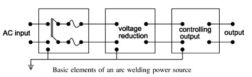
Ques.52. Calculate the force experienced by the conductor, with L = 0.5m and B = 4Wb/m2, when the armature current is 5 Amp?
- 5N
- 10N✓
- 15N
- 20N
The force acting on the current carrying conductor is given as F = B.I.L sinθ Where F = 4 × 0.5 × 5 F = 10 N
B = magnetic flux density = 4Wb/m2
L = Active length of the conductor = 0.5m
I = Magnitude of the current carrying by the conductor = 5 A
Ques.53. Maximum power will be developed when back emf is
- Equals to supply voltage
- Half to supply voltage✓
- Doubles to supply voltage
- All option are correct
Suppose a d.c motor of resistance R is connected to a d.c. supply of V volts. Let the armature current be la and the back E.M.F developed be Eb. The voltage equation of the D.C motor is given as V = Eb + IaRa ————(1) Multiplying both sides of the above equation by Ia we get VIa = EbIa + I2aRa ———(2) This equation is called the power equation of a dc motor. VIa = electric power supplied to the armature (armature input). EbIa = power developed (mechanical power) by armature (armature output). I2aRa = Electric power wasted in the armature (armature copper loss) Thus out of the armature input, a small portion is wasted as I2aRa loss, and the remaining portion EbIa is converted into mechanical power within the armature. Now the mechanical power developed by the motor is Pm = EbIa Putting the value of Pm in equation 2 we get VIa = Pm + I2aRa or Pm = VIa − I2aRa Since V and R are fixed, power developed by the motor depends upon armature current. For maximum power, dPm ⁄ dIa should be zero. dPm ⁄ dIa = VIa − I2aRa = 0 dPm ⁄ dIa = V − 2IaRa = 0 IaRa = V/2 Putting the value of IaRa in equation 1 we get V = Eb + V/2 Eb = V/2 Hence mechanical power developed by the motor is maximum when back e.m.f. is equal to half the applied voltage. In practice, we never try to achieve this condition because in that case, the armature current will be much more than the normal current. Moreover, half of the input power would be wasted in the armature resistance in the form of heat, and taking other losses into the consideration, the motor efficiency will be below 50 percent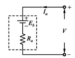
Ques. 54. Force on a Conductors is
- Unidirectional✓
- Bidirectional
- Either of these
- None of these
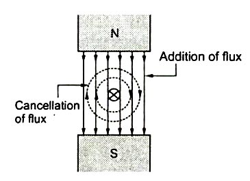
Force on a Conductor is Unidirectional. If the electric current passes through a conductor, a magnetic field immediately builds up due to the motion of electrons. When a magnetic field is applied to a conductor, the electrons will start moving in the conductor. Magnetic Effect of Electric Current When an electric current flows through a conductor, the magnetic field is set up all along the length of the conductor. Fig. shows the magnetic field produced by the current flowing in a straight wire. The magnetic lines of force are in the form of concentric circles around the conductor. The direction of lines of force depends upon the direction of current and may be determined by the right-hand rule. Hold the conductor in the right-hand with the thumb pointing in the direction of the current. Then the fingers will point in the direction of the magnetic field around the conductor. Applying this rule to Fig., it is clear that when viewed from left-the hand side, the direction of magnetic lines of force will be clockwise. Let a straight conductor, carrying a current is placed in a magnetic field. The current-carrying conductor also produces its own magnetic field around it. Now there is the presence of two magnetic fields namely due to the permanent magnet and due to the current-carrying conductor. These two fluxes interact with each other. Such interaction is shown in Fig. This interaction as seen is in such a way that on one side of the conductor the two lines help each other while on another side the two try to cancel each other. This means on the right side of the conductor shown in Fig. the two fluxes are in the same direction and hence assisting each other. As against this on the Left-side of the conductor, the two fluxes are in opposite directions hence trying to cancel each other. Due to such interaction on one side of the conductor, there is the accumulation of flux lines (gathering of the flux lines) while on the other side there is the weakening of the flux link. The following points may be noted about the magnetic effect of electric current: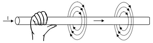
Force on a current-carrying conductor placed in the magnetic field
Ques.55. No-load saturation characteristics are plotted between
- No-load voltage and field current✓
- No-load voltage and armature current
- Short circuit current and field current
- Short circuit current and armature current
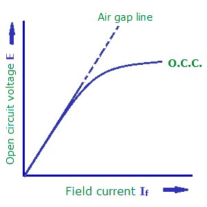
No-load saturation characteristic of generator: This curve is also called magnetic characteristic or open-circuit characteristic (O.C.C.). It shows the relationship between the e.m.f. generated on no-load in the armature, Eo, and the field current if, with the speed remaining constant. The curve depends on the material used in the electromagnets. It is practically the same, whether the generator is separately-excited or self-excited. Generally, it starts from zero but in a self-excited DC generator, it has residual voltage and starts a slightly higher value.
At the low voltage and, hence, low levels of flux, the major reluctance (magnetic resistance) of the magnetic circuit is the airgap. In the linear portion of the open-circuit curve, terminal voltage and flux are proportional to the field current. This portion of the open-circuit saturation curve, which is linear, is called the “airgap line.”
At higher voltages as the flux increases the stator and rotor iron, saturate, and additional field current is required to drive magnetic flux through the iron. This is due to the apparent higher reluctance of the magnetic circuit. Hence, the upper part of the curve bends away from the airgap line at an exponential or logarithmic rate, dependent on the saturation effect in the stator and rotor. Without the presence of iron in the circuit, the airgap line would continue on linearly, meaning that the terminal voltage and machine flux would increase in linear proportion to the increase in field current.
Ques.56. Transformer oil is used as
- An insulator
- A coolant
- Both insulator & coolant✓
- Inert Medium
Transformer oil is used in the oil-filled transformer and in some other systems such as high voltage capacitors, fluorescent lamp ballasts, circuit breakers etc. Transformers generate a lot of heat by dropping high voltage to low voltage. The heat has to be removed or the copper will melt and electrical contact will be lost. In comes oil. Oil has a very good heat transfer coefficient (removes heat easily), does not conduct electricity at all (so electrical shorts won’t occur), and is selected to have a high boiling point, so it remains a liquid inside the transformer. It is also very chemically stable, so there is no breakdown over time. There are two main functions of the transformer oil:- The transformer oil should possess the following properties:
Ques.57. Which is to be short-circuited on performing a short circuit test on a transformer?
- Low voltage side✓
- High voltage side
- Primary side
- Secondary side
The low voltage side is to be short-circuited on performing a short circuit test on a transformer. Short circuit test or Impedance test is performed to determine Normally the short circuit test is performed on HV winding by short-circuiting the LV winding because if we perform a test on the low voltage side a very high current is going to flow so to measure this huge current will need a large measuring instrument such as an ammeter. Therefore, the TEST of the short circuit is done on the high voltage side, which equivalently meant low current(a transformer is a constant power device). So the maximum current won’t be more than some 5-50 ampere and can be easily measured. The SC test can be done on either side and will be reflecting the same results, but it is always recommended to work safely, thus shorting the LV side, is the safest way. Note that the voltage required to pass the rated current is about 5 to 10% of the rated voltage. Let explain it with an example: Consider a 22 kVA, 11 kV/220 V, single-phase transformer on which a short circuit test is to be performed. The rated currents on HV and LV sides are: 22000/11000 = 2 A and 22000/220 V = 100 A respectively. If you short the HV side you need to apply about 11 to 22 V to get a current of 100 A on LV side. So the wiring used should be able to carry this high current. You need an ammeter to measure 100 A. You need a wattmeter with a current coil rated for 100 A and a pressure coil rated at around 25 V. (Difficult to get) If you short the LV side you need to apply about 550 to 1100 V to get a current of 2 A on the HV side. You need an ammeter to measure 2 A. You need a wattmeter with a current coil rated for 2 A and a pressure coil rated at around 1100 V.
⇒ Copper loss at any load
⇒ Equivalent impedance (Zo1 or Zo2)
⇒ Leakage reactance (Xo1 or Xo2)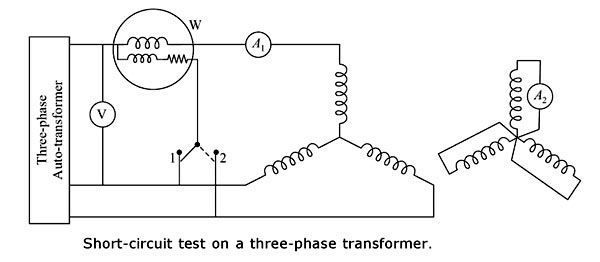
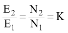
Ques.58. A Single-Phase 50Hz transformer has high voltage and low voltage windings of 2200/220 V. What is the Transformation ratio?
- 10
- 1/10✓
- 1
- None of these
The transformer ration K is given as 220/2200 = K K = 1/10
Ques.59. If the air gap in an induction motor is increased _____
- The speed of rotor increases
- The power factor will decrease✓
- The windage losses will increase
- Current drawn by the motor increase
If the air gap of an induction motor is increased, the following will happen: In summary, the maximum available torque will decrease, the power factor will worsen and the motor will run with increased slip. So it is always good performance-wise to run with as small an air gap as possible, which will reverse all of these effects. But if the air gap is too small, rotor cooling is compromised, and if the rotor expands through overheating (e.g. by exceeding the recommended maximum number of starts per hour) the rotor can “pole” by rubbing or jamming with the stator.
Ques.60. In three-phase induction motor reversing the supply in two of the phases is called as
- Pole changing
- Plugging✓
- increase the torque
- To control current
Plugging is also called reverse current braking. It is known that the rotor of a polyphase induction motor develops torque in the same direction as the rotating magnetic field set up by the stator winding. Also if any two stator leads are reversed, the rotating magnetic field is also reversed. lf therefore, the pair of stator leads are reversed while a motor is rotating, torque is suddenly-produce opposite to the original direction of rotation. This reverse torque causes rotation in the opposite direction as soon as the motor stops, therefore provision must be made to disconnect the stator completely from the supply lines when the motor stops. On reversing the armature current the supply voltage to the armature and back emf developed in it are additive. So, this condition is worse than the starting condition as the applied voltage to the armature is approximately double (V+E = 2V) to the supply voltage. Hence Plugging in induction motor braking is applied by just reversing the supply phase sequence by interchanging connections of any two phases of the stator, we can attain plugging braking of an induction motor. Due to the reversal of phase sequence, the direction of the rotating magnetic field gets reversed. This produces a torque in the reverse direction and the motor tries to rotate in opposite direction. This opposite flux acts as the brake and it slows down the motor. During plugging the slip is (2 – s), if the original slip of the running motor is s. Slip during motoring = s =(Ns – Nr)/Ns or During Plugging Slip =(-Ns – Nr)/-Ns = (Ns + Nr)/Ns = (2 – s) Note: The method can be applied to both squirrel cage as well as wound rotor induction motors. The disadvantages of this method are: 1. The kinetic energy of the motor is dissipated in the external resistance in the form of heat. So, this method of braking is inefficient. 2. The braking in this method fails in case of failure of the supply.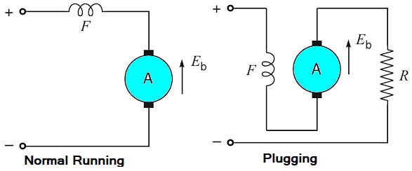
Nr/Ns = (1 – s)


