
Ques.71. The conductivity of aluminum as compared to copper is
- 1
- 0.7
- 0.6✓
- 0.5
Copper For many years, copper has been the most satisfactory conductor for electrical purposes. Its electrical and mechanical properties, coupled with comparative cost benefits, made it almost exclusively used universally. Its conductivity is high, surpassed only by that of silver and some other rare metals; indeed, its conductivity is used as a reference for that of other materials. Aluminum Although the conductivity of aluminum is only some 61 percent that of copper i.e (0.6), the weight of aluminum is only about one-third that of copper. For the same conductivity, therefore, an aluminum conductor would weigh only about half as much as copper, although somewhat larger in diameter. The breaking strengths of aluminum and soft-drawn copper are also about the same. The result is that these two materials are economically competitive as conductors.
Ques.72. What is the type of insulator used for holding the HT overhead conductor on the straight running of poles?
- Post insulators
- Pin-type insulators✓
- Stay insulators
- Shackle insulators
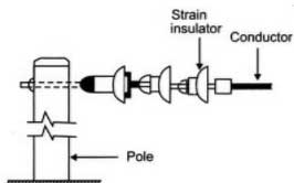
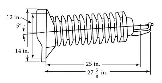
Pin-type insulators are used for holding the HT overhead conductor on the straight running of poles. An insulator is a material that prevents the flow of an electric current and can be used to support electrical conductors. The function of an insulator is to provide for the necessary clearances between the line conductors, between conductors and ground, and between conductors and the pole or tower. Insulators are made of porcelain, glass, and fiberglass treated with epoxy resins. However, porcelain is still the most common material used for insulators. The pin insulator gets its name from the fact that it is supported on a pin. The pin holds the insulator, and the insulator has the conductor tied to it. The pin type has a steel bolt or pin connected to the porcelain by a soft metal. These insulators are used for intermediate poles of a line, i.e. for straight runs of the line. They may be made in one piece for voltages below 23 kV, in two pieces for voltages from 23 to 46 kV, in three pieces for voltages from 46 to 69 kV, and in four pieces for voltages from 69 to 88 kV. Pin insulators are seldom used on transmission lines having voltages above 44 kV. The glass pin insulator is mainly used on low-voltage circuits. The porcelain pin insulator is used on secondary mains and services, as well as on primary mains, feeders, and transmission lines. The material most commonly used for Pin-type Insulator is porcelain and Glass. The insulators are shaped from the raw material (a mixture of clay, finely ground feldspar, and silica in water) are dried, dipped in liquid glaze, and then fired at a very high temperature. The glaze forms a glass-like coating providing a surface to which dirt cannot readily stick. It also improves the strength of the insulator so that fracture is more difficult. Glass is an alternative material. Toughened glass insulators have a higher breakdown strength under electrical stress than porcelain and if damaged shatter like the windscreen of a motor vehicle when it is hit by a stone. The glass pin insulator is mainly used on low-voltage circuits. Shackle Type Insulator:- This insulator is also known as a spool insulator. Basically, this insulator is used for low voltages, i.e., below 11 kV. It can be used in both directions either vertical or horizontal. Strain type insulators are used for handling the mechanical stress at the angle position of the line i.e Dead end, intermediate anchor tower, corner, sharp curve. These insulators reduce the excessive tension on the line under such abnormal conditions. For low voltage lines below 11 kV shackle insulators are used but for higher voltages strain insulators are used. Post type Insulator:- A modified version of the pin-insulator is known as the post-insulator. The post-type insulators are used for distribution, sub-transmission, and transmission lines and are installed on wood, concrete, and steel poles. The insulator base is different depending on the pole type. The insulators are available in the vertical, horizontal, or intermediate mounting types (slight angle such as 5° to horizontal) to suit the conductor configuration. The line post insulators are constructed for vertical or horizontal mounting. The line post insulators are usually made as one-piece solid porcelain units. The figure shows a typical post-type porcelain insulator. Suspension insulators consist of a string of interlinking separate disks made of porcelain. A string may consist of many disks depending on the line voltage. For example, on average, for 115-kV lines usually seven disks are used; however, for 345-kV lines usually, 18 disks are used.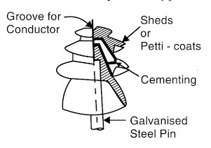
Ques.73. The type of lamp having the highest illumination efficiency is
- Mercury vapor lamp
- Incandescent Lamp
- Sodium Vapour Lamp✓
- Fluorescent Lamp
A sodium-vapor lamp features well monochromaticity, high brightness, and good luminous efficiency. It is a gas-discharge lamp. The efficiency of the sodium-vapor lamp is related to the sodium-vapor pressure. Two peaks exist at the pressure of 0.5 and 104 Pa. Low-pressure sodium lamp has higher efficiency and better monochromaticity than high-pressure sodium (HPS) lamp. The luminous efficiency of a low-pressure sodium vapor lamp is about 200 lumen/watt. Mercury Vapor lamp:- Mercury-vapour lamps were the first commercialized HID(High-Intensity Discharge) lamps, which use an electric arc through mercury vapor to produce light. It originally produced a bluish-green light, but more recent versions can produce clear white light. Compared to incandescent and most fluorescent lights, it is more energy efficient with luminous efficacies lying in the range of 35-65 lumens/watt and lifetime at about 24,000 h. Compact fluorescent (CFL) Compact fluorescent (CFL) lamps are becoming more popular. Incandescent lamps Incandescent lamps have been around for a long time and are still commonly used, but they don’t perform as well as some of the other lamps on the market.
Ques.74. At what level of current flow during electric shock death is possible
- 1 to 8 milli-amp
- 50 to 100 milli-amp✓
- 10 to 20 milli-amp
- 20 to 50 milli-amp
Electric Shock Hazards Injuries related to electrical shocks are common accidents occurring every year and everywhere, especially when it comes to occupational incidents. Most workplaces nowadays are equipped with an electrical source and open electrical equipment that may expose workers to the hazard of being electrocuted. Electricity refers to the flow of electrons through a material. The force that drives the electrons and makes electron flow possible is known as the voltage. Any material or substance through which electricity flows is called a conductor. Examples of conductors used in electrical work include copper and aluminum. These substances offer very little resistance to electron flow. Some materials offer very high resistance to electron flow and are classified as insulators. Examples are plastic, rubber, and porcelain. Electricity flows along a path or circuit. Typically, this path begins with a power source and follows through a conductor to a load. The path then flows back along another conductor to the Power source. A very important point to consider at this time is that the human body can, under certain conditions, readily become a conductor and a part of the electrical circuit. When this happens, the result is often fatal. Electrons flowing in the circuit have no way of detecting the difference between human beings and electrical equipment. The resistance of the Human dry skin is about 100,000 Ohms to 500,000 ohms, during the perspiring or sweaty hand the resistance becomes 1000 ohms. When the body is completely wet or under the water the resistance drops down to 150 ohms. The human body reacts differently to the level of current flowing through it. The data shows some typical reactions when a body is subjected to various amounts of current Remember that a milliampere (mA) is 1/1000 (0.001) of an ampere. It is a very small amount of current. ⇒ Less than 1mA = No Sensation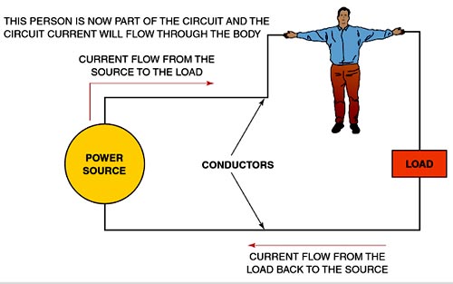
⇒ 1 mA = Possibly a tingling sensation
⇒ 5 mA = Slight shock felt; not painful, but disturbing; most people can let go; strong involuntary reactions may lead to injuries
⇒ 6 to 30 mA = Can definitely feel the shock; it may be painful and you could experience muscular contraction (which could cause you to hold on)
⇒ 50 to 150 mA = Painful shock, breathing could stop, severe muscle contractions; death is possible.
⇒ 1000 to 4300 mA = Heart convulsions (ventricular fibrillation), paralysis of breathing; usually means death
⇒ 10,000 mA = Cardiac arrest and severe burn deathly
Ques.75. The material used for making small rating fuses is
- Aluminum
- Copper
- Silver
- Lead and Tin✓
Fuse is the current interrupting device that breaks or opens the circuit (in which it is inserted) by fusing the elements when the current in the circuit exceeds a certain value. Fuse is the simplest and cheapest device used for interrupting an electrical circuit under the condition of short-circuiting, or excessive overload, current magnitudes. A fuse is a safety device having a short length of a thin, tin-plated copper wire having a low melting point, which melts and breaks the circuit if the current exceeds a safe value. The thickness and length of the fuse wire depend on the maximum current allowed through the circuit. An electric fuse works on the heating effect of current. The fuse for protecting our domestic wiring is fitted just above our main switch on the switchboard. A fuse wire is connected in series in the electric circuits. Fuse wire is made with an alloy of lead and tin having a low melting point and low resistance (although the resistance of fuse wire is higher than that of electrical appliances). If due to any malfunction or fault, excessive current begins to flow through the circuit, the fuse wire immediately melts due to the heat generated by the flowing current. The circuit is broken and the excess current, which may damage equipment is prevented from flowing. It is used for Overload and for short-circuit protection in high voltage (upto 66 kV) and for low Voltage (upto 120 V – 240 V) installations/circuits. Characteristics of a fuse are:-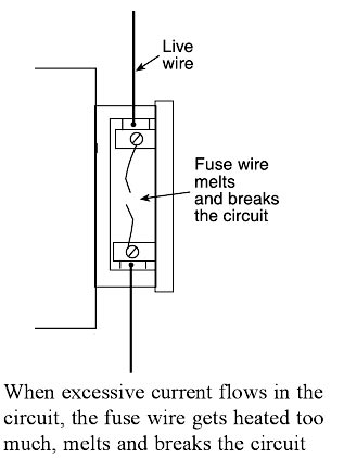
Ques.76. In the circuit breaker, the arcing contacts are made of
- Electrolytic copper
- Copper tungsten alloy✓
- Aluminum alloy
- Porcelain
The Arcing contacts are designed to prevent the main contacts from being damaged and can be made of alloys of silver, cadmium, tungsten, and zinc. The tungsten, cadmium, and zinc make the arcing contacts harder, so when the contacts open and close they will not deteriorate as quickly. A breaker has two sets of contacts per phase called main concur and arcing contacts. Each set of contacts consists of one faced contact and one moving contact. The main contacts carry the continuous current. The arcing contacts are used during closing and opening. The main contacts arc silver-plated copper and the arcing contacts are made up of heat-resistant material like copper tungsten, or silver tungsten. While opening, the main contacts open first and there is negligibly arcing at the main contact tips as a parallel path is available through the arcing contacts. This is because of the compression spring. While making, the arcing contacts are made first and the main contacts are made following it. This can be clearly seen in Fig. The making duty of the breaker is much more difficult than the breaking duty. When the circuit breaker is closed onto a fault there can be arcing at the contact tips and the current would be very high (2.5 to 2.8 times the symmetrical breaking current). The arc produced while making or breaking the fault current is highly intense. The temperature in the arc varies from 6000°C at the periphery of the arc to as large as 15000°C at the core of the arc. Because of this reason special arcing contacts are used. Also, the Arcing contacts are designed to prevent the main contacts from being damaged and can be made of alloys of silver, cadmium, tungsten, and zinc. The tungsten, cadmium, and zinc make the arcing contacts harder, so when the contacts open and close they will not deteriorate as quickly. When the circuit breaker opens, the part of the main contact first and then the arcing contacts part, “drawing out” the arc across the air gap. When the circuit breaker closes, the arcing contacts meet first, creating the bridge for the arc to cross. This way, the main contacts are protected from carrying the arc, preserving them.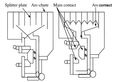
Ques.77. The main consideration in designing a Distributor is
- Transmission Voltage
- Resistance
- Voltage Drop✓
- Current Carrying capacity
REQUIREMENT OF THE DISTRIBUTION SYSTEM When a distribution system is designed, the most important factor of design must be the continuity of supply to various locations. Some important requirements for a good distribution system are discussed as follows: A distributor is a conductor from which tappings are taken for supply to the consumers. In fig, AB, BC, CD, and DA are the distributors. The current through a distributor is not constant because tappings are taken at various places along its length. Note:- Feeders: When the feeder of a distribution system is designed, its current-carrying capacity is the main factor while voltage drop is not so important. This is because voltage drops can be compensated by the various voltage regulating equipment placed at the substations. 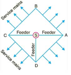
Ques.78. When in dry conditions human body resistance is around
- 100 KΩ✓
- 10 KΩ
- 1 KΩ
- 0
Electricity refers to the flow of electrons through a material. The force that drives the electrons and makes electron flow possible is known as the voltage. Any material or substance through which electricity flows is called a conductor. Examples of conductors used in electrical work include copper and aluminum.
These substances offer very little resistance to electron flow. Some materials offer very high resistance to electron flow and are classified as insulators. Examples are plastic, rubber, and porcelain. Electricity flows along a path or circuit. Typically, this path begins with a power source and follows through a conductor to a load. The path then flows back along another conductor to the Power source.
A very important point to consider at this time is that the human body can, under certain conditions, readily become a conductor and a part of the electrical circuit. When this happens, the result is often fatal. Electrons flowing in the circuit have no way of detecting the difference between human beings and electrical equipment.
The resistance of the Human dry skin is about 100,000 Ohms to 500,000 ohms, during the perspiring or sweaty hand the resistance becomes 1000 ohms. When the body is completely wet or under the water the resistance drops down to 150 ohms.
The human body reacts differently to the level of current flowing through it. The data shows some typical reactions when a body is subjected to various amounts of current Remember that a milliampere (mA) is 1/1000 (0.001) of an ampere. It is a very small amount of current.
Note:- For more info check question number 74.
Ques.79. The electric flux and field intensity inside a conducting sphere is
- Zero✓
- Maximum
- Uniform
- Minimum
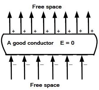
The electric flux and field intensity inside a conducting sphere is Zero. When the magnitude of the induced field becomes equal to that of the applied field, the net field intensity inside the conductor will become zero That is the Electric field due to the charges inside the conductor is directed opposite to the electric field outside due to which the field inside the conductor originated. Remember: The charges move in a conductor so as to kill the external field Consequently, no further movement of charges will take place. That is, the static condition will be reached after a brief transient period during which charges move to the surfaces. External field lines terminate on the bottom surface and emerge from the top surface, as shown in the figure. Since field intensity inside a good conductor is zero, the potential gradient, which is numerically equal to the field intensity, is also zero. Accordingly, the potential has the same value everywhere inside a good conductor.Why is the electric field inside a conductor zero?
Ques.80. The enclosure of motor is made from
- Copper
- Aluminum
- Cast Iron✓
- Laminated Sheath
The main function of a motor enclosure is to protect the motor from environmental impacts such as rain, corrosive, rusty, and many more in which the motor is installed. It also protects the windings from fumes, splashing fluids, and airborne solid as it is an important safety factor. Generally, the enclosure of the motor is made up of cast iron. Types of the enclosure of motor


