Ques.81. The unit of plane angle is
- Radian✓
- Steradian
- Lux
- WB
The Radian is the SI unit for plane angles. The radian was formerly an SI supplementary unit, but this category was abolished in 1995 and the radian is now considered an SI-derived unit. Note:- Steradian:- Steradian is the SI unit of Solid angle. Lux:- Lux is the unit of Illumination. Wb (Weber):- Weber is the SI unit of magnetic flux.
Ques.82. The air delivery of the fan is indicated by
- km3/min
- mm3/min
- m3/min✓
- cm3/min
CMM – “cubic meters per minute” is the amount of air that is moved by a ceiling fan. (or). The ability of a fan to convert the electrical energy into moving air or The volume of air in cubic meters that the fan can move in a minute at a defined speed. The efficiency of a fan is determined by calculating the amount of air it movers divided by the power it consumes. Fans are rated for how much air they can move in a given amount of time. The most common spec is cubic meter per minute (m3/min). To find the proper size fan, calculate how many cubic meters are in the area you want to cool (just multiply length x width x height), of the entire house or the room.
Ques.83. Which of the following will need the highest level of illumination?
- Proof reading✓
- Bedrooms
- Hospital wards
- Railway platforms
Illumination levels The intensity of lighting required to perform any job satisfactorily will depend on the nature of the job. Some jobs which involve extremely delicate and precise movement surgery, proofreading for example, require very high levels of illumination. Other, less delicate, the job does not require such high levels. Proofreading is the process of reviewing the final draft of a piece of writing to ensure consistency and accuracy in grammar, spelling, punctuation, and formatting. [ninja_tables id=”28473″]
Ques.84. The source of illumination for a cinema projector is
- Incandescent lamp
- Mercury vapor lamp
- Sodium lamp
- Carbon arc lamp✓
Carbon arcs operate by ionizing air molecules (which carry the current between the carbon electrodes) to incandescence. To ignite the lamp, the rods are touched together, thus allowing a relatively low voltage to strike the arc. The rods are then slowly drawn apart, and electric current heats and maintains an arc across the gap. The tips of the carbon rods are heated and the carbon vaporizes. The carbon vapor in the arc is highly luminous, which is what produces the bright light. The rods are slowly burnt away in use, and the distance between them needs to be regularly adjusted in order to maintain the arc. The carbon arc lamp was mainly used in the cinema projector. A carbon electrode projector produces the best possible light, a pure white with even brightness. But the rods are consumed in less than an hour (another reason for changeovers), and their burning produces carbon monoxide. The carbon-arc played a significant role until the introduction of the short-arc xenon discharge lamp in 1951.
Ques.85. As the thickness of the part to be welded increases which of the following parameter(s) for AC welding should also increase?
- Voltage
- Current✓
- Frequency
- All of the above
Welding Current:- The current within the usable range is selected according to the electrode size, type of metal transfer, and base metal thickness. When the current is too low, the molten metal fails to wet the joint surface and causes a lack of fusion. When the current is too high, it gives rise to spatters Porosity and poor weld bead profile. According to the law of thermal similarity, the weld time is proportional to the square of the thickness of the sheets being welded. For example, if the thickness of the sheets being welded is doubled, the weld time should be increased by four times. In addition, current and electrode size should be doubled. This approach is based mainly on differences in bulk heating due to changes in sheet thickness and doesn’t consider contact resistances between the sheets. As the sheet thickness increases, a higher welding current is required to establish a nugget. This necessitates the use of a larger diameter electrode. The use of a higher welding current coupled with the use of a larger diameter electrode creates a bigger weld. Large diameter welds have higher load-bearing ability. The weld size can also be increased by increasing the welding current. However, after a certain maximum weld size is achieved, a further increase in the welding current results in the expulsion of molten weld metal. This occurs because the high welding current creates so much melting at the sheet interfaces that the amount of molten metal becomes too great to be supported at the faying surfaces.
Ques.86. Which of the following motor is suitable for driving cranes, hoists, centrifugal pumps, conveyor belts etc.?
- DC series Motor✓
- DC Shunt Motor
- DC compound Wound Motor
- Any of these
Among the d.c. motors, the series motors, and cumulative compound motors are most preferred for crane operations. The motors have good starting torque, high torque capacity at light loads, the simple arrangement of braking, electric braking at low speeds is possible. The only disadvantage is that the motors are less stable while the regenerative braking. So additional stabilizing circuits are necessary. Advances made in the technology of solid-state devices have enabled the use of thyristor converters and choppers for driving the d.c. motors used in cranes and hoists with good accuracy, reliability, and efficiency. Ward Leonard system is commonly employed for elevators, hoists, and main drive in steel mills, as this method can give unlimited speed control in either direction. Since the generator voltage can be varied gradually from zero, no extra starting equipment is required to start up the main motor smoothly. Hoists Hoists are a means of transporting materials or passengers vertically by means of a moving level platform. Materials hoist come in basically two forms i.e static and mobile models. The hoist can be driven by petrol, diesel, or electric motor and can be of a cantilever or enclosed variety. Crane A crane is the type of machine mainly used for handling heavy loads in different industry branches: metallurgy, paper, and cement industry. By the construction, cranes are divided into overhead and gantry cranes Belt Conveyors are designed to carry a wide variety of bulk materials and packed bags, boxes, pouches, etc for various industries. Belt conveyors are economical and efficient conveying of materials over long distances, either in horizontal or limited inclines. It conveys a high capacity of materials for lumpy ore stone, coal, and wood logs. Torque and power requirements for crane and Hoist drives and Belt conveyor Speed control is an essential feature in crane drives. It is required for allowing soft starting and stopping of the travel motions for enabling its correct positioning of the load. For the lifting drive the speed control in a wide speed range, from zero to nominal values, is required. Because of the precision when raising and lowering load, the possibility of working at a very low speed and hold a load at the standstill is required, without using the mechanical brakes. The torque and power that have to be delivered by the drive may be obtained from the torque versus speed characteristic from the load (so-called mechanical characteristics) and the differential equation of motion. During acceleration, kinetic energy is stored in the system. To stop the crane, this energy must be absorbed by the drive. The acceleration and retardation must be uniform. For exact positioning of loads creep speeds must be possible. The motion of the crane is in all three dimensions. The drive must have high speeds in both directions horizontal and vertical. The speed must be constant while lowering the loads. Mechanical braking must be available in an emergency. Due to the heavy inrush of current at starts, fluctuations in supply voltage are possible. The drive motor must be capable of withstanding such fluctuations. Crane hooks have to be moved in three dimensions in space: two in a horizontal plane and a vertical hoist motion. The characteristics of long travel and cross travel motions are: Hoist motion: This is required to lift and put down the loads without damage. The characteristics of this motion therefore are: The nature of the duty cycle and conditions under which it has to work form the basis of the requirements of the crane. In steel plants, the cranes to be used must satisfy the following: Note:- Centrifugal pumps and fans are constant displacements with normal starting torque devices, therefore, DC shunt Motor or squirrel cage induction motor is usually preferred.
Ques.87. The main application of indirect-arc furnace is to melt
- Iron
- Steel
- Non-ferrous metals✓
- None of these
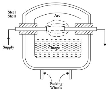
ARC FURNACE The principle of the arc furnace can be described as follows: If the air gap is subjected to a very high voltage, the air gets ionized due to the electrostatic force. The ionized air is a conducting material with a continuous spark. The current starts flowing through the air gap in the form of the continuous spark, which is called an arc thereby producing intense heat. The graphite or carbon is used as an electrode and the temperature obtained from the arc is between 3000°C and 3500°C. There are two types of arc furnaces: Indirect-Arc Furnace In this case, the arc is formed between the two electrodes, and the heat thus produced is passed on to the charge by radiation. The fig. shows a single-phase indirect-arc furnace that is cylindrical in shape. The arc is struck by short-circuiting the electrodes manually or automatically for a moment and then withdrawing them apart. The arc does not come in contact with the metal to be melted, the heat is given to the charge by radiation from the arc and reflection from the walls of the furnace. The furnace is designed to give a rocking motion as the melting proceeds, thus quickening up the melt by distributing the heat more rapidly. Since in this furnace, the charge is heated by radiation only, its temperature is lower than that obtainable in a direct arc furnace. Such furnaces are mainly used for melting non-ferrous metals such as copper base alloy, although they can be used in iron foundries where small quantities of iron are required frequently. The capacity of an indirect-arc furnace is normally up to a maximum of 1000 kg are available. Due to their limited capacity and noisy operation, these furnaces are generally being replaced by other types such as induction furnaces.
Ques.88. The tips of the electrodes, for spot welding, are made of
- Carbon
- Copper alloy or pure copper✓
- Mica
- Porcelain
The tips of the electrodes, for spot welding, are made of copper alloy or pure copper. Spot welding is one of the oldest welding processes. Spot welding is one form of resistance welding, which is a method of welding two or more metal sheets together without using any filler material by applying pressure and heat to the area to be welded. When similar materials are spot welded, then the highest resistance is between the interfaces of the two sheets, provided the correct welding conditions are used. When welding dissimilar metals, the maximum resistance may not exist at the interface; instead, it may be located within one of the metals if it has a higher specific resistance than the other metal. A lap weld consists of two or more materials that are overlapped on top of one another. The edge of one material is melted and fused with the surface of another material. Among the various type of spot welding, lap welding and multiple lap welding is most popular. The spot welding tips are made of copper with alloying elements of chromium, cobalt, and beryllium. The welding tongs and tips deliver the following functionalities: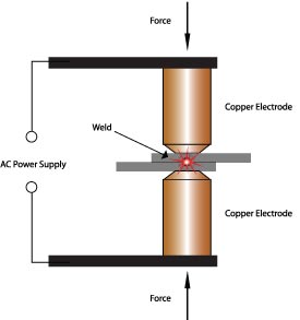
Ques.89. The germanium crystal behaves as an insulator at
- 0°K✓
- 273° K
- 5° K
- None of these
The germanium crystal behaves as an insulator at 0° K. Effect of Temperature On Resistance The electrical resistance changes with the change of temperature. The resistance does not only increase with the rise in temperature but it also decreases in some cases. In fact, for the different type of materials, the amount of change in resistance due to change in temperature is different which are discussed as follow. Metal: The resistance of all pure metals increases linearly with an increase in temperature over a limited temperature range. At low temperatures, the ions are almost stationary. As the temperature increases, the ions inside the metal acquire energy and start oscillating about their mean positions. These vibrating ions collide with the electrons Hence resistance increases with an increase in temperatures. Alloy: The resistance of almost all alloys increases with an increase in temperature but the rate of change of resistance is less than that of metals. In fact, the resistance of certain alloys such as Manganin, Eureka, and Constantan show practically no change in resistance for a considerable range of temperature. Due to this property, the alloy is used to manufacture the resistance box. Semiconductor, Insulator, and Electrolyte: Semiconducting elements are tetravalent i.e. there are four electrons (valence electrons) in their outermost shell. The atomic pattern of atoms in Si and Ge crystals is a tetrahedral structure such that each atom shares one of its 4 electrons with each neighbor and vice versa. The resistance of semiconductor, Insulator, and Electrolyte(silicon, Glass, Varnish, etc) decrease with an increase in temperature. At zero temperature, the semiconductor behaves as a perfect insulator. As the temperature increases, some of the electrons acquire energy and become free for conduction. Hence, conductivity increase and resistance decrease with an increase in temperature. When the temperature is raised above 0 k, electrons gain thermal energy and start jumping into the conduction band and participate in conduction
Ques.90. In p-n junction with no external voltage, the electric field between the acceptor and the donor ions is called a
- Barrier✓
- Threshold
- Peak
- Path
The potential difference created across the P-N junction due to the diffusion of electrons and holes is called a potential barrier. For Ge VB = 0.3 V and for silicon VB = 0 7 V Consider a semiconductor bar consisting of a PN junction. Assume that the entire sample is a single crystal and the PN junction is just formed. The left half section of the semiconductor bar is a P-type and the right half-section of the semiconductor bias is N-type. The P-type region consists of majority carriers (holes) and negatively charged acceptor ions (negative ions). The N-type region contains majority carriers (electrons) and positively charged donor ions (positive ions). The minority carriers in the P-type and N-type regions are ignored. The figure shows the formation of the depletion layer in a PN junction when no external voltage is applied to the PN junction. Just after the formation of the PN junction, the conduction and valence bands of P-type and N-type semiconductor materials overlap, and the following processes take place. 1. The P-type region has more holes and the N-type region has more free electrons. There is a difference in concentrations in the P-type region and N-type region. The difference in concentration generates a concentration gradient across the junction. Therefore, there is a diffusion of mobile charge carriers across the junction. 2. The electrons and holes can move at random in all directions due to thermal agitation. Therefore, some carriers are able to cross over the junction. 3. The holes will diffuse to the N-type region from the P-type region and combine with the free electrons. 4. The free electrons will diffuse to the P-type region from the N-type region and they combine with holes. 5. The diffusion of holes and free electrons across the junction takes place for a short time. After recombination of holes and free elections, a limiting force is developed. Due to this force, the depletion layer stops further diffusion of holes and free electrons from one region to the other region. Just after the formation of the PN junction, the holes in the P-type region and the free electrons in the N-type region will diffuse with each other and disappear due to recombination. Therefore, the negative acceptor ions in the P-type region and positive donor ions in the N-type region are left uncovered in the junction region. Some holes will diffuse to the N-region and they are replaced by the uncovered positive charge of the donor ions. In the same way, some electrons will diffuse into the P-type region and are replaced by the uncovered negative charge of the acceptor ions. After the initial diffusion of free electrons and holes, their further diffusion across the junction is stopped. Consequently, a region that consists of the uncovered acceptor and donor ions is developed in the junction area. This region is called the depletion region, as shown in Fig. As the depletion region consists of immobile positive and negative ions, it is called the space-charge region. Since the uncovered charges within the depletion region exist in the form of parallel rows of opposite charges, it is also called the depletion layer. The depletion layer behaves just like an insulator. Due to the presence of rows of fixed charges, the depletion layer develops a capacitance. The width of the depletion layer depends upon the doping level of the impurity in N-type and P-type semiconductors. When the doping level is high, the thinner depletion layer will be developed and vice versa. The reason for the thinner depletion layer is that the highly doped PN junction contains a large number of electrons and holes and diffusing charge carriers (free electron or hole) cannot cross the junction for recombination. The electrons and holes recombine near the junction and thus cancel each other out. This results in opposite charges of each side of the junction, creating a depletion region, or space charge region. The depletion layer acts as a barrier that opposes the flow of electrons from the n-side and holes from the p-side. To overcome this barrier potential, we need to apply an external voltage that is greater than this barrier potential. When the voltage applied to the p-n junction diode is greater than the barrier potential, the electric current starts flowing.PN junction Depletion Region and Potential Barrier