Ques.11. Which of the following is TRUE in case of Substitution theorem?
The initial condition of the rest of the circuit changes, if a network element is replaced by a voltage source having an equal voltage as the voltage across the element at every instant of time.
The initial condition of the rest of the circuit changes, if a network element is replaced by a voltage source having an equal current as the voltage across the element at every instant of time.
The initial condition of the rest of the circuit remains the same if a network element is replaced by a voltage source having an equal voltage as the voltage across the element at every instant of time.✓
The initial condition of the rest of the circuit changes, if a network element is replaced by a voltage source having an equal voltage as the current across the element at every instant of time.
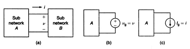
The substitution theorem states that in the branch equivalence, the terminal voltage and current must be the same ” According to the theorem, the components in a network can be interchanged, so long as the terminal current and voltage are maintained.
This theorem can be considered a generalization of the Thevenin or Norton statements.
With the substitution theorem, we can, for instance, realize a source conversion (which is sometimes referred to as a separate theorem, the source conversion
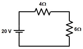
Let us take an example as shown in the figure
Applying voltage division rule the voltage across 4 ohms and 6 ohms resistance is
V4Ω = (20 × 4) ⁄ (4 + 6)
V4Ω = 8 V
V6Ω = (20 × 6) ⁄ (4 + 6)
V6Ω = 12 V
Now current in the circuit
I = V/R = 20/10 = 2A
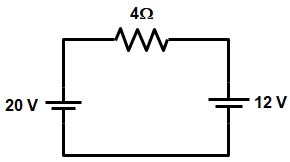
Now if we replace the 6Ω resistance with a voltage source of 12 V as shown in fig
Now the voltage and current across the 4ohm resistance will be
V4Ω = 20 − 12 = 8 ohms
I4Ω = V/R = 8/4 = 2A
Hence from the above example, it is clear that by replacing 6Ω resistance by 12 V cell the voltage across the 4ohm resistor remains the same. Hence the substitution theorem is proved.
Ques.12. Which of the following theorem states that the sum of the instantaneous power in ‘n’ number of branches of an electrical network is zero?
Compensation
Maximum power transfer
Superposition
Tellegen’s✓
Tellegen’s theorem states that the sum of the products of instantaneous branch voltages and branch currents in a network is zero.
$\sum\limits_{k = 1}^B {{V_K}{I_K} = 0}$
where V1, V2, … VB is instantaneous branch voltages and I1, l2, … lB is the instantaneous value of branch currents we know that the product (VK, IK) is the instantaneous power. Tellegen’s theorem tells us that summation of instantaneous powers for all the branches of a network is zero.
We know the active elements give (deliver) the power and passive element talkie (receive the power. In the simple sentence, Tellegen’s theorem states that given power by the battery is equal to taken power by the passive elemental.
Note: Sometimes battery is taking power, in this case, the battery is charging (current is entering into the battery positive terminal).
Tellegen’s theorem depends on KCL and KVL but not on the type of the elements. Tellegen theorem can be applied to any network linear or non-linear, active or passive, time-variant or time-invariant. This theorem is based upon the conservation of energy.
Kirchhoff’s Voltage Law (KVL,) or Kirchhoff’s Loop Rule. This law is based on the conservation of energy and may be stated as under:
In any closed electrical circuit or loop, the algebraic sum of all the electromotive force (e.m.f s) and voltage drops in resistors is equal to zero, i.e., in any closed circuit or loop.
The algebraic sum of e.m.f s + Algebraic sum of the voltage drops = 0
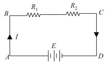
The validity of Kirchhoff’s voltage law can be easily established by referring to the loop ABCDA shown in Fig.
If we start from any point (say point A) in this closed circuit and go back to this point (i.e., point A) after going around the circuit, then there is no increase or decrease in potential. This means that the algebraic sum of the e.m.f.s of all the sources (here only one e.m.f. source is considered) met on the way plus the algebraic sum of the voltage drops in the resistances must be zero. Kirchhoff’s voltage law is based on the law of conservation of energy, i.e., the net change in the energy of a charge after completing the closed path is zero.
V1 + V2 − V = 0
or
Kirchhoff’s voltage law is also called as loop rule.
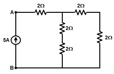
Ques.14. Determine the voltage in volt between points A and B for the given electrical circuit.
40
20✓
60
30
To identify whether the resistance is connected in series or in parallel consider the following method
Use one color for each continuous wire
DO NOT cross any circuit elements
Any element that shares the same two colors are in parallel
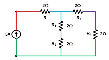
Now the circuit will look as shown below
The black wire is connected to only the resistance of R1 & R2 hence these two resistance are in series, similarly the resistance R3 and R4 are connected to thevioletwire hence these two resistance are also connected in series.
R1 + R2 = 2 + 2 = 4Ω
R3 + R4 = 2 + 2 = 4Ω
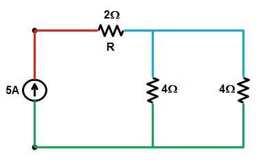
Now the circuit is redrawn as shown in the figure
As you can see from the above figure the two resistance of 4 ohms each share two common colorsi.eblueandgreenhence these two resistance are in parallel.
R = 4 || 4 = (4 × 4) ⁄ (4 + 4) = 2Ω
Now both 2Ω resistance are connected in series hence equivalent resistance will be
Req = 2 + 2 = 4Ω
∴ The voltage V = I.R = 5 × 4
V = 20 V
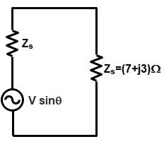
Ques.15. Determine the value of the source impedance ( in Ohms) for transmitting the maximum power to the load in the circuit given below.
7 + j3
7 − j3✓
3 + j7
3 − j7
For maximum power transfer, the impedance of the load must be equal to the complex conjugate of the impedance of the output. Thus, if the output impedance of a network has the value R + jX, for maximum power transfer, the load should have an impedance of R – jX. This implies that, if the output impedance has a capacitive component, the load must have an inductive component to obtain maximum output power. It can be seen that the simpler statement given above is a special case of this result in which the reactive component of the output impedance is zero. Hence for maximum power transfer, load impedance must be equal to the complex conjugate of Source impedance
As we know The impedance of input of something to which a signal is applied is a measure of how much power that input will tend to draw (from a given output voltage). This impedance is known as the load impedance.
Therefore Zs = ZL*
Zs = (7 + j3)*
Zs = (7 − j3)Ω
Hence the value of source resistance is 7Ω and the value of source reactance is 3Ω
Ques.16. Determine the value of power dissipated (in W) through the 20Ω resistor of the circuit given below.
30
45✓
60
75
Applying KVL at the circuit as shown in the figure we get
Loop 1
10(I1 − I2) = 20
I1 − I 2 = 2 ———(1)
Loop 2
20I2 + 10(I2 − I1) = 10
3I2 − I1 = 1 ———-(2)
Adding equation 1 and 2 we get
I2 = 1.5 A
Power dissipated through the 20Ω resistor will be
P = I22R
P = (1.5)2 × 20
P = 45 watt
Ques.17. Determine the power dissipated (in W) by the 25Ω resistor in the circuit given below.
0✓
25
125
156.25
Changing the current source into the equivalent voltage source as shown in the figure
These two voltage sources are connected in series with their emfs in opposition. Current flows in the direction of the greater emf and is limited to
I = (50 − 50) ⁄ (10 + 25 + 5)
I = 0
Hence the power dissipated by the 25Ω resistance will be Zero.
Note:- Voltage is the important thing that causes the current to flow. The important thing to be noted in the question is equal voltage so it clearly implies that there is no potential difference across the resistor and hence there is no current flow ideally.
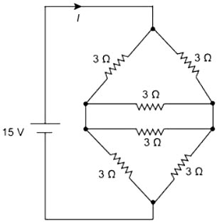
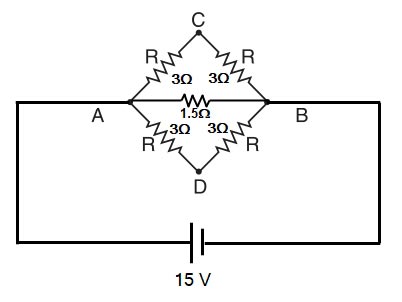
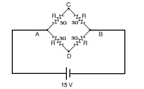
Ques.18. Determine the total current “I” (in A) supplied by the voltage source in the circuit given below.
3
4
5✓
6
Solving the circuit
The two resistance of 3Ω are in parallel therefore
3 || 3 = (3 × 3) ⁄ (3 + 3) = 1.5Ω
It is a balanced Wheatstone bridge. Therefore, points C and D are at the same potential. Since no current flows in the branch CD, this branch is ineffective in determining the equivalent resistance between terminals A and B and can be removed.
The branch ACB (3 + 3 = 6Ω) is in parallel with branch ADB (3+ 3 = 6Ω)
∴ RAB = (6 × 6) ⁄ (6 + 6) = 3Ω
Hence the current is I = VAB ⁄ RAB = 15/3 = 5 A
IAB = 5A
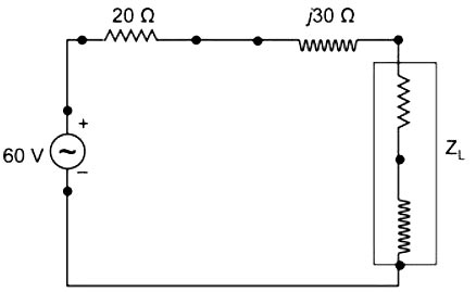
Ques.19. Determine the maximum power (in W) transferred from the source to the load of the circuit given below.
18
30
45✓
90
For maximum power transfer, the impedance of the load must be equal to the complex conjugate of the impedance of the output. Thus, if the output impedance of a network has the value Rth + jX, for maximum power transfer, the load should have an impedance of Rth – jX.
Therefore ZL = Zs*
ZL = (20 + j30)* = (20 − j30)
Now the current I is given as
I = V ⁄ (ZS + ZL)
I = 60 ⁄ (20 + j30 + 20 − j30)
I = 60 ⁄ 40 = 1.5 A
P = I2Rth = 1.52 × 20
P = 45 Watt
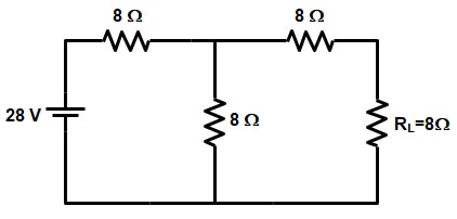
Ques.20. Determine the Norton’s current (in A) and Norton’s resistance (in Ω) respectively, for the given electrical circuit.
1.167, 12✓
2.345, 14
4.434, 15
2.346, 10
To determine the Norton current short-circuit the load resistance as shown in the figure
Now the equivalent resistance of the network is
R = R1 + (R2 || R3)
R = 8 + (8 × 8) ⁄ (8 + 8)
R = 8 + 4 = 12Ω
Source current IS = V/R = 28/12 = 2.33A
Now the Norton current IN = Current flowing through resistance R3
Applying current division rule
IN = IS × R3 ⁄ (R2 + R3)
IN = 2.33 × 8 ⁄ 16
IN = 1.167 A
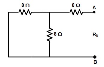
Now to find the Norton resistance remove the load resistance RL and replace the source voltage by its internal resistance.
RN = R3 + (R1 || R2)
RN = 8 + (8 × 8) ⁄ (8 + 8)
RN = 8 + 4 = 12Ω
Note:- Since all the option given for this question is different either find Norton current or Norton’s resistance