Ques 11. Which one of the following statements is TRUE?
Kirchhoff’s Law is not applicable to the circuit with the passive elements
Kirchhoff’s Law is not applicable to the circuit with the non-Linear resistance.
Kirchhoff’s Law is not applicable to the circuit with the non-Linear resistance
Kirchhoff’s Law is not applicable to circuits with the distributed elements✓
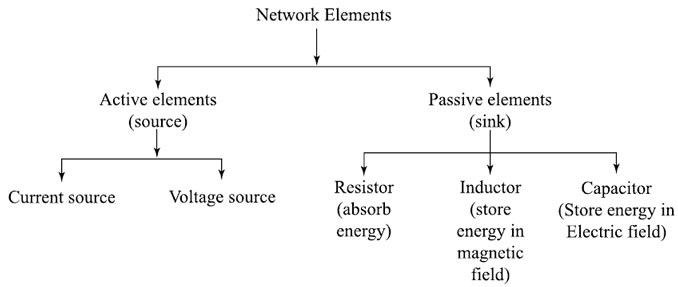
Types of Elements in a Network Circuit
Passive Network/Element:- Passive network is one, which contains no source of emf in it i.e., R, L, C.
An element that is capable of receiving power is called a passive element Ex: Resistor, Inductor, Capacitor.
Active Network/Element:- Active network is one that contains one or more than one source of emf, then the network is called an active network.
An element that is capable of supplying power is called an active element.
The network element can further be classified into more different groups
Linear or Non-Linear
Unilateral or Bilateral
Time-variant or Time invariant
Lumped or distributed Network
Lumped Elements:- When it is possible to separate the elements of a network physically like resistors, inductors, Capacitors, etc. the elements are called as lumped elements. Kirchhoff’s law is only applicable to the circuit with lumped elements.
Distributed Elements:- When it is not possible to separate the elements of a network physically the elements are known as distributed elements. The best example of such a network is a transmission line where the resistance, inductance, and capacitance of a transmission line are distributed all along its length and cannot be shown as a separate element, anywhere in the circuit.
Ques 12. Which one of the following is a passive element to an electric circuit?
Current source
Voltage source
Resistors✓
Battery
Passive Network/Element:- Passive network is one, which contains no source of emf in it i.e., R, L, C.
An element that is capable of receiving power is called a passive element Ex: Resistor, Inductor, Capacitor.
Active Network/Element:- Active network is one that contains one or more than one source of emf, then the network is called an active network.
An element that is capable of supplying power is called an active element. Examples are the current source, voltage source, battery, cell, Transistor, etc.
Ques 13. Which one of the following is the mathematical expression of Ohm’s Law?
V = I
V = R/I
V = I.R✓
V = R
Ohm’s law states that the electric current flowing through the conductor is directly proportional to the potential difference between its two ends when the temperature and other physical parameters of the conductor remain unchanged.
OR
V = IR
Ques 14. Determine the current (in A) that flows through a 15 Ohms resistance, when the potential difference between the terminals of the resistors is 60 V.
3
2
4✓
6
Given
Resistance R = 15 ohms
Potential Difference V = 60 V
Current I = ?
According to the Ohm’s Law
I = V/R = 60/15 = 4A
I = 4A
Ques 15. Which of the following is the CORRECT formula for permeance?
I/H
B/H
φ/Fm✓
Fm/L
Reluctance
Similar to the resistance characteristic in electricity, we have reluctance in magnetism which is the property of the substance that opposes the magnetic flux through it.
The reluctance of any part of a magnetic circuit may be defined as the ratio of the drop in magnetomotive force to the flux produced in that part of the circuit. It is measured in ampere-turns/Weber and is denoted by S.
Reluctance = m.m.f ⁄ flux
Reluctance is dependent on:
Nature of the substance.
Area of the cross-section of the material through which flux is passing (a).
Length of the magnetic path.
Permeance
The reciprocal of reluctance is called permeance and is a measure of the readiness with which the magnetic flux is developed. it is analogous to conductance in an electric circuit and is measured by Weber/ampere-turn.
Permeance = 1/Reluctance
∴ Permeance = flux ⁄ m.m.f
Ques 17. Determine the power (in W) dissipated by a 16 ohms resistor, when the potential difference between the ends of the resistors is 32 V.
66
68
62
64✓
Given
Resistance = 16 ohms
Potential difference V = 32 V
∴ Power dissipated by the resistor
P = V2 ⁄ R = (32)2 ⁄ 16
P = 64 Watt
Ques 18. Which of the following represents the quality factor of a series RLC circuit?
Ques.19. What will be the value of average power (in Watt) of a sinusoidal voltage applied across a series circuit is 20 sinωt V and the current flowing the circuit is 10 sin(ωt + 60)A?
50
60
80
100✓
Given
The instantaneous value of Voltage V = Vmsinωt = 20 sinωt = 20 V
The instantaneous value of voltage I = Imsin(ωt + φ) = 10 sin(ωt + 60) = 10 A
Ques 20. Which of the following is used for the measurement of the insulation resistance?
Megger✓
Wattmeter
Ammeter
Voltmeter
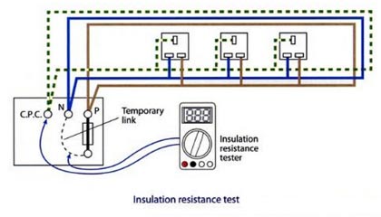
Testing of Insulation Resistance of Complete Installation to Earth
The principal purpose of testing the insulation is to verify that there are no inadvertent connections between live conductors and between live and Earth before the installation is energized. Tests are required between live conductors (e.g. between phases and between phase(s) and neutral) and between all live conductors and Earth.
Insulation resistance of the installation depends on many factors such as atmospheric conditions, humidity, dirt, etc. As such its calculation is not possible, but it can be readily measured. Normally the insulation resistance is quite high and can be measured by an instrument called “megger“ usually used for the measurement of high resistance.
The main object of performing this test is to ascertain whether the complete wiring is sound enough to avoid leakage current. As per the Indian electricity rules, the leakage current of installation should not exceed 1/5000 of the maximum supply-demand of the consumer. As such the insulation resistance of the complete installation to earth should not be less than 1 MΩ. Insulation resistance test must be conducted on dc voltage of value not less than twice the standard supply voltage. However, it need not exceed 500 V for medium voltage circuits.
(vi) Live and neutral wire to be shorted together.
Testing of Insulation Resistance Between Conductors
After testing the insulation resistance of installation to earth, the insulation resistance between line and neutral should be measured. The major object in conducting this test is again to ensure that the insulation is quite sound between the conductors and there are no chances of any appreciable leakage current between them.
This test should be carried out under the following conditions of installation
(i) The Main switch is off.
(ii) The main fuse has withdrawn.
(iii) All other fuses in their position.
(iv) All switches in on position.
(v) All lamps from the holders were removed.
(vi)Two terminals of the meager are connected to the line and neutral wire.
Insulation resistance measured under the above condition by a megger should not be less than 50 MΩ divided by the number of outlets(points + switches). However, it need not be more than 1 MΩ.