SSC JE electrical 2019 question paper with solution SET-1
Ques.1. If admittance Y= a + jb, then a =?
Reactance
Conductance
Resistance
Susceptance
Answer.2. Conductance
Explanation:-
Admittance (Y) is the reciprocal of the impedance of a circuit. Admittance of an AC circuit is analogous to the conductance of a DC circuit. The unit of Admittance is Simen or MHO
Admittance = 1/Z simen
Y = Conductance ± J Susceptance
Or the Admittance can be written as
Y = (G ± J B) Simen
Now comparing the above equation by the given equation in the question i.e Y= a + jb
∴ a = G = Conductance
Ques.2. At f = _____R – L – C series circuit operates at unity power factor.
1 ⁄ RLC
1 ⁄ LC
1/RC
1/2π√LC
Answer.4. 1/2π√LC
Explanation:-
In an electrical system, capacitor and inductor are two such devices that store energy in different forms. The inductive and capacitive reactances are opposite to each other in two senses:
The magnitude of inductive reactance (XL) increases with frequency, while the magnitude of capacitive reactance (XC) decreases with frequency.
The angle of XL is + 90° whereas the angle of XC is −90°.
At some frequency, the inductive reactance is equal to the capacitive reactance. When circuit is operated at a frequency where the reactive (imaginary) component of the total impedance is zero, the circuit is said to be resonant. Note that the impedance circuit at
Series RLC Resonance
The resonance of a series RLC circuit occurs when the inductive and capacitive reactances are equal in magnitude but cancel each other because they are 180 degrees apart in phase. Since in resonance condition, the Inductive reactance XL is equal to capacitive reactance XC i.e XL = XC
Ques.3. A 200 V d.c machine as Ra = 0.5 Ω and its full-load Ia= 20A. Determine the induced e.m.f when the machine acts as a motor
190 V
200 V
210 V
215 V
Answer.1. 190 V
Explanation:-
Given Data
Voltage Va = 200 v
Armature Resistance Ra = 0.5Ω
Armature Current Ia = 20 A
Induced EMF = Ea = ?
The Induced EMF of a DC machine working as a Motor is
Ea = Va − IaRa
Ea = 200 − 20 × 0.5
Ea = 190 V
Ques.4. The amount of AC content present in the DC output of a rectifier is given by
Ripple factor
Peak factor
Form factor
Power factor
Answer.1. Ripple Factor
Explanation:-
Ripple factor: The output of the rectifier is of pulsating d.c. type. The amount of a.c. content in the output can be mathematically expressed by a factor called the ripple factor (γ). The ripple factor expresses how much successful the circuit is, in obtaining pure d.c from a.c. input.
Less is the ripple factor, better is the performance of the circuit.
Ripple Factor γ = R.M.S value of a.c component of output ⁄ Average or d.c component of the output
Ques.5. If an AC circuit is supplied with an active power of 500 W and reactive power 500 VAR, then the load power factor of the circuit is
0
1
0.5
1/√2
Answer.4. 1/√2
Explanation:-
Given
Reactive Power Q = 500 VAR
Active Power P = 500 W
Power Factor of an AC circuit when active and reactive power is given
Power Factor = cos [tan−1(Q/P)]
Power Factor = cos [tan−1(1)]
Power Factor = cos [tan−1(1)]
Power Factor = cos 45°
Power factor = 1/√2
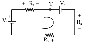
Ques.6. With the current direction marked in the circuit shown, the net voltage applied is
V1
−(V2 − V1)
(V2 − V1)
V2
Answer.2. −(V2 − V1)
Explanation:-
Net voltage = −V2 + V1
Net voltage = −(V2 − V1)
Ques.7. The skin effect does not depend upon
Operating voltage
The diameter of the conductor
Frequency
The shape of the conductor
Answer.1. Operating voltage
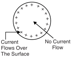
When DC flows in the conductor, the current is uniformly distributed over the whole cross-section of the conductor. But the flow of AC in the conductor is non-uniform, due to which the outer filaments of the conductor carry more current than the filaments closer to the center of a conductor. In fact in the AC system, no current flows through the core and the entire current is concentric at the surface regions. The tendency of alternating current to concentrate near the surface of a conductor is known as the skin effect.
Due to skin effect, the effective area of cross-section of the conductor through which current flows is reduced. Consequently, the resistance of the conductor is slightly increased when carrying an alternating current.
Cause of Skin Effect
The cause of skin effect can be easily explained. A solid conductor may be thought to be consisting of a large number of filaments, each carrying a small part of the current. The inductance of each filament will vary according to its position. Thus, the filament near the center is surrounded by a greater magnetic flux and hence have larger inductance than that near the surface. The high reactance of the inner filament causes the alternating current to flow near the surface of the conductor. This crowding of current near the conductor surface is the skin effect.
Due to non-uniformity of current, skin effect, the flux linkages are reduced and thus skin effect reduces the effective internal reactance. The inner filaments carrying currents give rise to flux which links the inner filaments only whereas the flux due to the current-carrying outer filaments enclose both inner and outer filaments.
Depending factor Skin Effect
The skin effect depends on the following factors:
Nature of material
The diameter of the wire – increases with the diameter of the wire
Frequency – increases with the increase in frequency
The shape of wire – It less for stranded conductor than the solid conductor
At low frequencies, the skin effect is very small. In fact, it is of importance only with the high frequencies or with the solid conductors of the large cross-section. For commercial frequency of 50 Hz or lower, the increase in effective resistance is negligible for solid copper conductor up to 10 mm in diameter, about 2.5% for 20 mm diameter, and 8% for 25 mm diameter. The skin effect is much smaller with stranded conductors than with solid conductors. The skin effect increases in cross-section, permeability, and in supply frequency.
Ques.8. If dΦ is the luminous flux incident normally on an area dA, then Illuminance is given as
dΦ ⁄ dA
Φ × A
dA ⁄ dΦ
dΦ − dA
Answer.1. dΦ ⁄ dA
Explanation
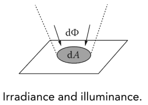
Luminous flux measures the total radiant power reaching a surface, but without regard to surface position: the power might be concentrated on only part of the surface or spread evenly across it.
Irradiance (Ee) or illuminance (Ev) is the density of incident radiant flux or luminous flux at a point on a surface and is defined as radiant flux or luminous flux per unit area, as given by
E = dφ/dA
where (dφ) is the radiant flux or luminous flux incident on an element dA of the surface containing the point. The unit of irradiance is Wm−2, and that of illuminance is lux
Ques.9. The ratio of conductor voltage and the voltage across the disc nearest to the conductor multiplied by the number discs are
String efficiency
Disc efficiency
Insulator efficiency
Transmission line efficiency
Answer.1. String Efficiency
Explanation
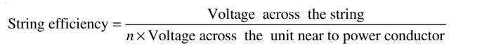
The non -uniformity in the voltage distribution over a string of suspension insulators is expressed in terms of a parameter called “string efficiency“.
The voltage across the unit nearer to the conductor is more than the voltage in the unit nearer to the support. This unequal potential distribution over the string is expressed in terms of string efficiency.
The efficiency of a string is defined as the ratio of voltage across the whole string to the product of the number of discs and the voltage across the disc nearest to the line conductor. Mathematically, it can be expressed as,
Where n = Number of the unit in the string
The more the value of the string efficiency, the more uniform is the voltage distribution across the string. For the ideal case, the string efficiency is 100% and the voltage across each disc of the string is equal. Practically various methods are used to obtain string efficiency as high as possible.
Ques.10. Lamp efficiency is measured in
Lux/watt
Candela/watt
Lumen/watt
Lumen/lux
Answer.3. Lumen/watt
Explanation:-
The luminous efficiency of an electric lamp is the ratio of the luminous flux (in lumen) emitted by the lamp to the electric power (watt) given to it i.e.
Luminous efficiency η = Luminous flux/Watt
Note:- Lumens is the unit of measurement for luminous flux, which is the total amount of visible light emitted by a source.