The ratio of luminous flux leaving the surface (Reflected Light) to the luminous flux incident on it (Incident Light) is known as the reflection factor.
The value of the Reflection factor is always less than 1.
Ques.32. A shaded pole motor is basically a motor
Synchronous
Shunt
Series
Single-phase induction
Answer.4. Single-phase induction
Explanation:-
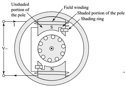
The shaded-pole motor is the original type of AC single-phase induction motor. Shaded pole-type single-phase induction motors are provided with shading rings on their poles which are the projected type of poles. The stator of such motors has projected poles like DC machines as shown in Fig. 5.7. The rotor is a squirrel cage type similar to that of split-phase-type motors. The poles are excited by giving a single-phase AC supply. A single-turn thick coil in the form of a ring called the shading ring is fitted on each side of every pole as shown. The portion of the poles where the shading ring is fitted is called the shaded portion, while the other portion is called the unshaded portion.
The shaded pole motor has the lowest starting torque as compared to the all single-phase induction motors.
Ques.33. H = ____is the expression for the magnetic field due to an infinite linear current-carrying conductor.
(μI ⁄ 2Πr) A/m
(μI ⁄ 2r) A/m
(I ⁄ 2Πr) A/m
(I ⁄ 2r) A/m
Answer.3. (I ⁄ 2Πr) A/m
Explanation:-
Magnetic Field Strength (H) gives the quantitative measure of strongness or weakness of the magnetic field.
H = B/μo
Where
B = Magnetic Flux Density
μo = Vacuum Permeability
Magnetic field due to infinite Linear current-carrying conductor is
B = μoI/2πr
B/μo = I/2πr
H = (I/2πr)A/m
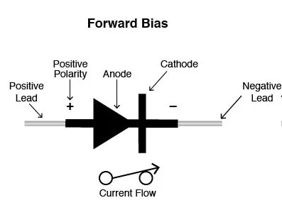
Ques.34. The direction of the arrow represents the direction of when the diode is forward biased.
N-type material
Conventional current flow
P-N Junction
P-type material
Answer.2. Conventional current flow
Explanation:-
The direction of the arrow represents the direction of the conventional current flow when the diode is forward biased.
Ques.35. Prevention of interference with neighboring telephone lines can be done by:
Using bundled conductors
Reducing skin effect
Reducing corona
Transposing transmission lines
Answer.4. Transposing transmission lines
Explanation:-
Interference of Transmission and communication line
In practice, it is observed that the power lines and the communication lines run along the same path. Sometimes it can also be seen that both these lines run on Sam supports along the same route. The transmission lines transmit bulk power with relatively high voltage. Electromagnetic and electrostatic fields are produced by these lines having sufficient magnitude. Because of these fields, voltages, and currents at induced in the neighboring communication lines. Thus it gives rise to interference c power line with the communication circuit.
“if the power line is running along the same route as the communication line, there will be interference in the communication line due to both electromagnetic and electrostatic effects.” The electromagnetic effect produces currents, which is superimposed on the communication signal, and thereby it is distorted. However, the electrostatic effect induces a voltage in the communication line, which may be dangerous in handling the telephone receiver.
Effect of Transposition:- The purpose of transposition is to balance the capacitances of the line so that the electrostatically induced voltages balance out in the length of a complete set of transposition, and this length is called a barrel.
Transposition also results in the decrease of electromagnetically induced e.m.f. on the wires, because of fluxes due to the positive and negative phase sequence, currents will add up to zero along the barrel.
Ques.36. Find the frequency of rotor induced EMF of a 3-phase, 440V, 50 Hz induction motor has a slip of 10%.
25Hz
2.5Hz
5Hz
50Hz
Answer.3. 5 Hz
Explanation:-
Given Data
Voltage = 440 V
Frequency = 50 Hz
Slip = 10% =0.1
Now,
Rotor frequency = slip × frequency
= 0.1 × 50 = 5 Hz
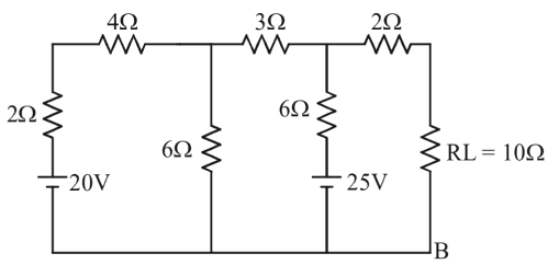
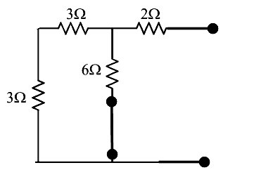
Ques.37. The Thevenin’s resistance as seen through the terminals A and B is:
5 Ω
6 Ω
4 Ω
7 Ω
Answer.1. 5Ω
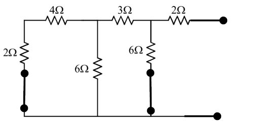
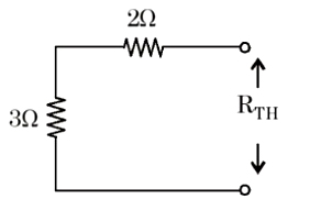
To find the Thevenin’s Resistance Rth replace all the voltage source by the short circuit remove the Load resistance i.e 10 Ω from the circuit as shown in the figure
Now the resistance 2Ω and 4Ω are in series and they both are connected in parallel to the resistance 6Ω i.e
R1= (2Ω + 4Ω)||6Ω
= 6Ω||6Ω
= (6 × 6)/(6 + 6)
R1 = 3Ω
Now the resistance 3Ω and 3Ω are in series and they both are connected in parallel to the resistance 6Ω i.e
R2= (3Ω + 3Ω)||6Ω
= 6Ω||6Ω
= (6 × 6)/(6 + 6)
R2 = 3Ω
At last, the resistance 2Ω and 3Ω are connected in series
Rth = 2Ω + 3Ω = 5Ω
Rth = 5Ω
Ques.38. Two inductors of 4H and 6H are connected in series. The equivalent inductance of this combination is
10 H
4 H
2.4 H
6 H
Answer.1. 10 H
Explanation:-
Total inductance when inductor are connected in series
L = L1 + L2
L = 4 + 6 =10H
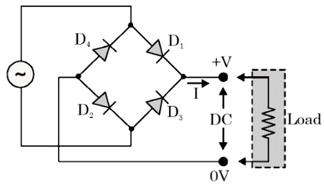
Ques.39. In the full-wave rectifier circuit shown in the figure, the diodes that conduct when the positive half-wave of AC signal applied are
D3, D4
D4, D1
D1, D2
D2, D3
Answer.3. D1, D2
Explanation:-
During the positive half cycle of the supply, diodes D1 and D2 conduct are forward biased and conduct current while diodes D3 and D4 are reverse biased and they act as an open circuit, the current flows through the load.
Ques.40. Which of the following lamps has the shortest/less life span in working hours?
Fluorescent lamp
Incandescent lamp
Sodium vapor lamp
Mercury vapor lamp
Answer.2. Incandescent lamp
Explanation:-
The lifespan of a bulb is referred to as “Average Rated Lifetime Hours” (ARL). Incandescent bulbs generally have the shortest lifespans. The average incandescent bulb light span is approximately 750-2,000 hours. Fluorescent lights generally have a life expectancy of 10,000 to 20,000 hours and other high-intensity lamps, such as high-pressure sodium, have greater than 20,000 hours of life expectancy.