
Ques 3(a). Describe the working principle and construction of an induction type wattmeter. What are the errors in induction type wattmeter, and how are they compensated?
Answer:
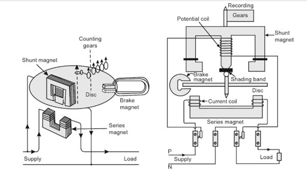
Induction-type Single-phase Energy Meter
An induction-type instrument can be used as an ammeter, voltmeter, or wattmeter, the induction-type energy meters are more popular. Induction-type single-phase energy meter is used invariably to measure the energy consumed in any AC circuit in a prescribed period where supply voltage and frequency are constant. The energy meter is an integrating instrument that measures the total quantity of electrical energy supplied to the circuit in a given period.
Principle
The basic principle of induction-type energy meter is electromagnetic induction. When AC flows through two suitably located coils (current coil and potential coil), they produce the rotating magnetic field that is cut by the metallic disc suspended between the coils, and thus, an emf is induced in the disc that circulates eddy currents in it. By the interaction of rotating magnetic field and eddy currents, electromagnetic torque is developed that causes the disc to rotate. This is the same principle that is applied in single-phase induction motors.
Construction
An induction-type single-phase energy meter, as shown in Figure 9.39, has the following main parts of the operating mechanism:
1. Driving system: The driving system of the meter consists of two electromagnets:
(a) Series magnet: It consists of a number of U-shaped laminations of silicon steel staggered together to form a core. A coil of thick wire having a few turns is wound on both the legs of the U-shaped magnet, as shown in Figure. This coil is connected in series with the load. Thus, it is excited by the circuit current I and is known as the current coil. This magnet is placed below the aluminum disc and produces the magnetic fielded proportional to and in phase with line current I.
(b) Shunt magnet: It consists of a number of M-shaped laminations of silicon steel assembled together to form a core. A coil of thin wire having a large number of turns is wound on the central limb of the magnet, as shown in Figure. This coil is connected across the load. Thus, it is excited by the current proportional to the supply voltage and is known as potential or pressure coil. This magnet is placed above the aluminum disc.
In order to obtain deflecting torque, current in the pressure coil must lag behind the supply voltage by 90°. For this, copper shading band (short-circuiting copper ring) is provided on the central limb of the shunt magnet. The phase difference of 90° is obtained by adjusting the position of this shading band. The shading band acts as short-circuited transformer secondary. Since its resistance is negligibly small as compared to its inductance, current circulating in the shading band lags behind the supply voltage nearly by 90°. Thus, shunt magnet produces a field φsh proportional to applied voltage. This field is in phase with the current flowing through the pressure coil Ip but is in quadrature with the applied voltage.
2. Moving system: It consists of a light aluminum disc mounted on a vertical spindle. The aluminum disc is positioned in the air gap between the series and the shunt magnet. The spindle is supported by a cup-shaped jeweled bearing at the bottom end and has a spring journal bearing at the top end. Since there is no control spring, the disc makes continuous rotation under the action of deflecting torque.
3. Braking system: A permanent magnet positioned near the edge of the aluminum disc, as shown in Figure 9.39, forms the braking system. When aluminum disc moves in the field of the braking magnet, flux is cut and eddy currents are induced in the disc. The direction of induced currents is such that it opposes the rotation (Lenz’s Law), and thus braking torque is produced. Since the induced currents are proportional to the speed of the disc (N), braking torque (TB) jS proportional to the disc speed, that is, TB ∝ N
The position of braking magnet is adjustable, and therefore, braking torque can be adjusted by shifting the magnet to different radial positions. If the braking magnet is moved towards the center of the disc, flux cut by the disc is less. Further, this reduces the induced current, and thus, the braking torque is reduced. Hence, by the inward movement of the magnet, braking torque decreases but the speed of the disc increases and vice versa.
4. Recording mechanism: The function of recording or registering mechanism is to record continuously a number on the dial that is proportional to the revolutions made by the moving system. The number of revolutions of the disc is a measure of the electrical: energy passing through the meter.
Working of Induction type Energy Meter
Induction-type wattmeters have two laminated iron-core electromagnets. One of the electromagnets is excited by the load current, and the other by a current proportional to the voltage of the circuit in which the power is to be measured. The upper magnet which is connected across the voltage to be measured is named as the shunt magnet, whereas the other electromagnet connected in series with the load to carry load current is called the series magnet. A thin aluminum disc, mounted in the space between the two magnets is acted upon by a combined effect of fluxes coming out of these two electromagnets. In ac circuits, the interaction of these changing fluxes will induce Eddy-current within the aluminum disc.
The two voltage coils, connected in series, are wound in such a way that both of them send flux through the central limb. Copper shading bands fitted on the central limb of the shunt magnet makes the flux coming out of the magnet lag behind the applied voltage by 90°.
The series magnet houses two small current coils in series. These are wound in a way that the fluxes they create within the core of the magnet are in the same direction.
When the energy meter is connected in the circuit, the current coil carries the load current and pressure coil carries the current proportional to the supply voltage. The magnetic field produced by the series magnet (series coil) is in phase with the line current and the magnetic field produced by the shunt magnet (pressure coil) is in quadrature with the applied voltage (since the coil is highly inductive). Thus, a phase difference exists between the fluxes produced by the two coils. This sets up a rotating field that interacts with the disc and produces a driving torque, and thus, the disc starts rotating. The number of revolutions made by the disc depends upon the energy passing through the meter. The spindle is geared to the recording mechanism so that electrical energy consumed in the circuit is directly registered in kWh.
The speed of the disc is adjusted by adjusting the position of the braking magnet. For example, if the energy meter registers less energy than the energy actually consumed in the circuit, then the speed of the disc has to be increased that is obtained by shifting the braking magnet near to the center of the disc and vice versa.
Error in single-phase Energy Meter
(1) Phase Errors: Normally, the flux due to the shunt magnet does not lag behind the supply voltage by exactly 90° due to the fact that the coil has some resistance. Therefore, the torque is not zero at zero power factor. This is known as phase error and is compensated by means of an adjustable copper band placed over the central limb of the shunt magnet. Due to this reason, the shading ring is known as the power factor compensator.
(2) Speed Error: The speed error of the meter, when tested on a non-inductive load, can be eliminated by correctly adjusting the position of the braking magnet. Movement of the poles of the braking magnet towards the center of the disc reduces the braking torque and vice-versa.
(3) Friction Error: Frictional forces at the rotor bearings and in the register mechanism give rise to an unwanted braking torque on the disc rotor. This can be reduced by making the ratio of the shunt magnet flux and series magnet flux large with the help of two shading bands. Correct compensation is achieved when the rotor does not run on no-load with only supply voltage connected.
(4) Creeping Error: The slow but continuous rotation of the disc when only the pressure coils are excited but no current is flowing in the circuit is called “creeping”. It may be caused by various factors like incorrect friction compensation, vibration, stray magnetic fields, or due to the voltage supply being in excess of the normal.
To overcome this creeping effect on no-load, two holes are drilled in the disc on a diameter, i.e. on opposite sides of the spindle. This causes sufficient distortion of the field to prevent rotation when one of the holes comes under one of the poles of the shunt magnet.
(5) Temperature Error: The error due to temperature variations of the instruments are usually small because the various effects produced tend to neutralize one another.
Energy Meter Adjustment
Some adjustments are necessary for energy meters so that they give the correct reading, and their errors are within the permissible limits. These adjustments are given below:
- Preliminary Light Load Adjustment: The disc of the energy meter is so positioned that the holes are not under the electromagnets. Rated voltage is applied to the voltage coil with no current through the current coil. The light load device is adjusted until the disc just fails to start.
- Full-load Unity Power Factor Adjustment: For this adjustment, the voltage coil is connected across the rated supply voltage, and the rated full-load current at unity power factor is passed through the current coils. The position of the braking magnet is adjusted to vary the braking torque so that the meter revolves at the correct speed within the required limits of error.
- Lag Adjustment: For this adjustment, the voltage coils are connected across the rated supply voltage, and the rated full-load current is passed to the current coil at 0.5 (half) power factor lagging. Now the lag device is adjusted by altering the position of the short-circuiting coil, till the meter runs at the correct speed.
- Light-load Adjustment: This adjustment is used to compensate for friction and is in the form of a small iron vane fixed to the middle core of the pressure coil electromagnet, just above the disc or a closed conducting loop placed unsymmetrically with respect to the shunt magnet. The purpose of this is to distort slightly the field below the pressure coil magnet (or shunt magnet) and thus set up, in the direction of rotation, an extra torque sufficient to overcome the frictional torque of the meter.
Ques 3(b): The four ARMS of a Maxwell A.C bridge are as Follows:
AB and BC are non-Inductive resistors of 100Ω each. DA is a standard variable inductor, L of resistance 32.7Ω and CD comprise a standard variable resistor R in series with a coil of unknown impedance. Balance is obtained when L = 47.8 mH and R = 1.36Ω. Find the resistance and Inductance of the coil.
Answer:-
A Maxwell bridge is a modification to a Wheatstone bridge used to measure an unknown inductance (usually of low Q value) in terms of calibrated resistance and inductance or resistance and capacitance.
As in the balance condition of the Wheatstone bridge product of opposite arms resistance are equal i.e
R1R3 = R2R4
In Maxwell AC bridge in the two arms, there are two pure resistances so that for balance relations, the phase balance depends on the remaining two arms.
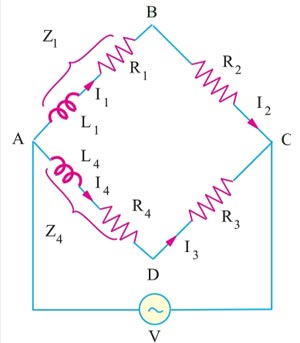
For the balanced condition of Maxwell AC bridge
Z1Z3 = Z2Z4
Where Z1 is the unknow Impedance
Z1 = R1 + JX1 = R1 + JωL1
Z4 is the know Impedance
Z4 = R4 + JX4 = R4 + JωL4
R2 and R3 = Known pure resistance
∴ (R1 + JωL1)R3 = (R4 + JωL4)R2
Equating Real and Imaginary part
R1R3 = R2R4
&
ωL1R3 = ωL4R2
L1R3 = L4R2
Hence, the unknown self-inductance can be measured in terms of the known inductance L4 and the two resistors. Resistive and reactive terms balance independently and the conditions are independent of frequency. This bridge is often used for measuring the iron losses of the transformers at audio frequency.
Now coming back to the question
The a.c. bridge is shown in Fig. Since the products of the resistances of opposite arms are equal
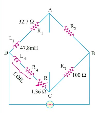
∴ R1R3 = R2R4
32.7 × 100 = (1.36 + R4)100
32.7 = 1.36 + R4
R4 = 31.34Ω
As discussed above
L1R3 = L4R2
L1 × 100 = L4 × 100
L4 = L1 = 47.8 mH
Or since the time constant are same
L1/32.7 = L4/(31.34 + 1.36)
47.8/32.7 = L4/(32.7)
L4 = 47.8 mH.
Ques 4(a). (i). What are the factors that control the speed of the DC Motor?
(ii). A 500 V shunt motor runs at its normal speed of 250 RPM when the armature current is 200 A. The resistance of armature is 0.12 Ω. Calculate the speed when a resistance is inserted in the field reducing the shunt field to 80% of normal value and the armature current is 100A.
Answer:- D.C. machines are generally much more adaptable to adjustable speed service. The ready availability of D.C. motors to adjustment of their operating speed over wide ranges and by a variety of methods is one of the important reasons for the strong competitive position of D. C. machinery in modern industrial applications.
Voltage Equation of DC Motor
The voltage equation of the DC Motor is given as
V = Eb + IaRa
The voltage V applied across the motor armature has to
(i) overcome the back e.m.f. Eb and
(ii) supply the armature ohmic drop IaRa
The above equation can also be written as
Eb = V − IaRa
Back EMF of DC Motor
When the armature of a d.c. the motor rotates under the influence of the driving torque, the armature conductors move through the magnetic field and hence e.m.f. is induced in them as in a generator. The induced e.m.f. acts in opposite direction to the applied voltage V (Lenz’s law) and is known as back or counter e.m.f. Eb.
[latex display=”true”]{E_b} = \dfrac{{P\Phi ZN}}{{60A}}[/latex]
Where
P – Number of poles of the machine
ϕ – Flux per pole in Weber.
Z – Total number of armature conductors.
N – Speed of armature in revolution per minute (r.p.m).
A – Number of parallel paths in the armature winding.
From the above equation, it is clear that the EMF of DC Motor is Directly proportional to the Number of poles of the machine (P), Flux per pole in Weber (ϕ), Total number of armature conductors(Z), and Speed of armature (N)
From the voltage equation and Back EMF equation, we can conclude that
[latex]\begin{array}{l}\dfrac{{P\Phi ZN}}{{60A}} = V – {\rm{ }}{I_a}{R_a}\\\\N = \dfrac{{V – {\rm{ }}{I_a}{R_a}}}{\Phi } \times \left( {\dfrac{{60A}}{{PZ}}} \right)r.p.m\\\\{E_b} = V – {\rm{ }}{I_a}{R_a}\\\\\therefore N = K\dfrac{{{E_b}}}{\Phi }\end{array}[/latex]
The above equation shows that speed is directly proportional to back e.m.f. E b and inversely to the flux Φ
N ∝ Eb /Φ.
[latex]N = \dfrac{{{E_b}}}{\Phi } \propto \dfrac{{V – {\rm{ }}{I_a}{R_a}}}{\Phi }[/latex]
But as the value of armature resistance Ra and series field resistance Rse is very small, the drop IaRa and Ia (Ra + Rse) is very small compared to applied voltage V. Hence, neglecting these voltage drops the speed equation can be modified as,
[latex]N \propto \dfrac{V}{\Phi }[/latex]
Thus the factors affecting the speed of a d.c. motor are:
- The flux Φ.
- The voltage across the armature
- The applied voltage V
Depending upon these factors We various methods of speed control are,
- Changing the flux Φ by controlling the current through the field winding called flux control methods.
- Changing the armature path resistance which in turn changes the voltage applied across the armature called rheostatic control.
- Changing the applied voltage called voltage control method.
Flux Control Method
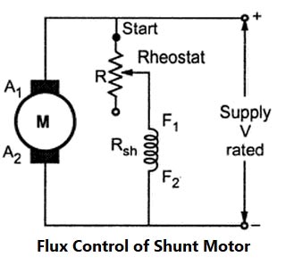
The speed of DC Shunt Motor is inversely proportional to the flux. The flux is dependent on the current through the shunt field winding. Thus flux can be controlled by adding a rheostat (variable resistance) in series with the shunt field winding. At Starting the rheostat R is kept at the minimum. The supply voltage is at its rated value. So the current through shunt field winding is also at its rated value. Hence the speed is also rated speed i.e at normal speed. When the resistance R is increased due to which shunt field current Ish decreases, hence decreasing the flux produced. As N =(I/Φ), the speed of the motor increases beyond its rated value. Thus by this method, the speed control above rated value is possible.
Armature voltage Control Method(Rheostatic Control)
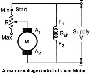
In DC shunt motor the speed is directly proportional to the voltage applied across the armature. As the supply voltage is normally constant, the voltage across the armature can be controlled by adding a variable resistance in series with the armature. Initially, the rheostat position is minimum and rated voltage gets applied across the armature. So speed is also rated. For a given load, armature current is fixed. So when extra resistance is added in the armature circuit, Ia remains same and there is the voltage drop across the resistance added (Ia R). Hence voltage across the armature decreases, decreasing the speed below normal value. By varying this extra resistance, various speeds below rated value can be obtained.
Ward-Leonard system.(Voltage Control)
The Ward-Leonard system comprises a fixed speed 3-phase AC induction motor driving; separately excited DC generator that, in turn, feeds a variable voltage to a shunt wound DC motor. So this is essentially a DC variable speed drive.
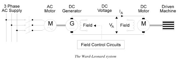
The basic principle of the DC variable speed drive is that the speed of a separately excited DC motor is directly proportional to the voltage applied to the armature of the DC motor. The main changes over the years have been concerned with the different methods of generating the variable DC voltage from the 3-phase AC supply.
In the case of the Ward-Leonard system, the output voltage of the DC generator, which is adjusted by controlling the field voltage, is used to control the speed of the DC motor.This type of variable speed drive had good speed and torque characteristics and could achieve a speed range of 25:1. It is no longer commonly used because of the high cost of the 3 separate rotating machines. In addition, the system requires considerable maintenance to keep the brushes and commutators of the two DC machines in good condition.
(ii)Given that
Supply voltage Vs = 500 V
Speed N1 = 250 RPM
Armature current Ia1= 200 A
Armature Resistance R1 = 0.12Ω
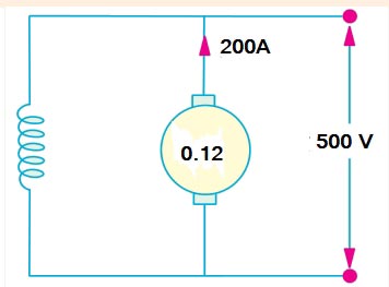
Back EMF of DC Motor is given as
Eb = V − IaRa
Eb = 500 − 200 × 0.12 = 478V
Now when the resistance is inserted in the field, Flux reduce to 80%
Flux Φ2 = 0.8Φ1
Armature current Ia2 = 100A
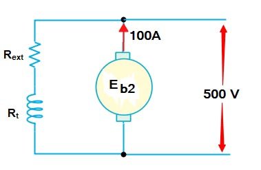
Back EMF
Eb = V − IaRa
Eb = 500 − 100 × 0.12 = 488V
As we Know that In DC motor the back EMF is directly proportional to the speed and flux.
E ∝ Nφ
[latex]\begin{array}{l}\dfrac{{{E_{b2}}}}{{{E_{b1}}}} = \dfrac{{{N_2}}}{{{N_1}}} \times \dfrac{{{\Phi _2}}}{{{\Phi _1}}}\\\\{N_2} = {N_1} \times \dfrac{{{E_{b2}}}}{{{E_{b1}}}} \times \dfrac{{{\Phi _2}}}{{{\Phi _1}}}\\\\{N_2} = 250 \times \dfrac{{488}}{{476}} \times \left( {\dfrac{{{\Phi _1}}}{{0.8{\Phi _1}}}} \right)\\\\{N_2} = 320{\rm{ R}}{\text{.P}}{\rm{.M}}\end{array}[/latex]
Ques 4(b). A three phase induction motor having a 6 pole, star connected stator winding runs at 240 V, 50 Hz supply. The rotor resistance and standstill reactance are 0.12Ω and 0.85Ω per phase. The ratio of stator to rotor turns is 1.8:1. Full load slip is 4%. Calculate the developed torque at full load.
Solution:-
Given
Number of poles P = 6
Frequency f = 50 Hz
Slip s = 4% = 0.04
Turns Ratio K : 1/1.8
Supply Voltage E1 = 240 Volt
Rotor Resistance R2 = 0.12 Ω
Rotor Reactance per phase at standstill X2 = 0.85 Ω
The turn ratio gives the induced EMF in the rotor as similar to transformer
[latex]\begin{array}{l}{\text{Turn Ratio = }}\dfrac{{{\text{Rotor turns per phase}}}}{{{\text{Stator Turns per Phase}}}}\\\\K = \dfrac{1}{{1.8}}\\\\K = \dfrac{{{E_2}}}{{{E_1}}}\\\\{E_2} = K \times {E_1}\\\\{E_2} = \dfrac{1}{{1.8}} \times \dfrac{{240}}{{\sqrt 3 }}\\\\{E_2} = 77V\end{array}[/latex]
Synchronous Speed of the Motor is given as
Ns = 120f/P
Ns = 120 x 50/6 = 1000 RPM
Converting RPM into RPS
= 1000/60 = 50/3 R.P.S
Now the Torque under Running Condition or torque under full load is given as
[latex display=”true”]{T_f} = \dfrac{3}{{2\pi {N_s}}}\frac{{s{E_2}^2{R_2}}}{{{R_2}^2 + {{\left( {s{X_2}} \right)}^2}}}[/latex]
Where
X2 = Rotor reactance per phase at the standstill
R2 = Rotor resistance per phase at the standstill
E2 = Rotor induced E.M.F per phase on standstill condition
[latex]\begin{array}{l}{T_f} = \dfrac{3}{{2\pi \left( {50/3} \right)}}\dfrac{{0.04 \times {{77}^2} \times 0.12}}{{{{0.12}^2} + {{\left( {0.14 \times 0.85} \right)}^2}}}\\\\{T_f} = 0.028 \times \dfrac{{0.796}}{{0.015}}\\\\{T_f} = 52.4{\text{ N – m}}\end{array}[/latex]