
Ques 3(a). A 100μA ammeter has internal resistance of 100Ω. For extending its range to measure 500μA, calculate the value of shunt resistance.
Answer.
Derivation used
The given figure shows the PMMC ammeter. The terminals AB forms the arm through which the current is to be measured. Im is the current through the meter, R is the resistance of the meter, Rsh is the shunt resistance and I is the current under measurement.
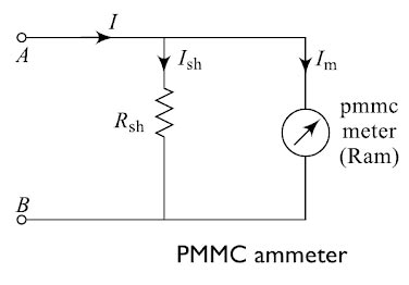
The low-value shunt connects in parallel to the ammeter because of which the voltage drops across the meter and shunt remain the same.The significant portion of the measurand current passes to the shunt because of the low resistance path and few amounts of current passes through the ammeter.
Let I= current to be measured.
Im = full-scale deflection current of ammeter
Ish = shunt current
Ram = resistance of PMMC; m
Rsh = shunt resistance,
Since the Rsh and meter are in shunt the voltage across them will be same and is given by
Ish x Rsh = Im x Ram
we have, I = Im + Ish
or Ish = I – Im
(I – Im)Rsh = Im x Ram
⇒ Now coming back to the question
A 100μA ammeter has an internal resistance of 100Ω as shown in the figure.
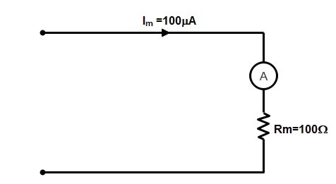
Now the total current to be measured is 500μA then the value of shunt resistance will be

[latex]\begin{array}{l}\left( {I{\rm{ }}-{\rm{ }}{I_m}} \right){R_s}{\rm{ }} = {\rm{ }}{I_m}{\rm{ }} \times {\rm{ }}{R_m}\\\\{R_s} = \dfrac{{{I_m}{R_m}}}{{\left( {I{\rm{ }}-{\rm{ }}{I_m}} \right)}}\\\\{R_s} = \dfrac{{{R_m}}}{{\left( {\dfrac{I}{{{I_m}}}} \right) – 1}}\\\\{R_s} = \dfrac{{100}}{{\left( {\frac{{500 \times {{10}^{ – 6}}}}{{100 \times {{10}^{ – 6}}}}} \right) – 1}}\\\\{R_s} = \dfrac{{100}}{{5 – 1}} = \dfrac{{100}}{4}\\\\{R_s} = 25\Omega \end{array}[/latex]
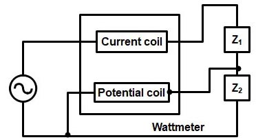
Ques 3(b). A wattmeter is connected as shown in figure. What will be the wattmeter reading of power consumed either by Z1 or Z2
A wattmeter is an instrument with a potential coil and a current coil so arranged that its deflection is proportional to VIcosφ, where V is the voltage (RMS value) applied across the potential coil, I is the current (RMS value) passing through the current coil, and θ is the angle between V and I . By inserting such a single-phase wattmeter to measure the average real power in each phase (with its current coil in series with one phase of the load and its potential coil across the phase of the load).
The current coil is the fixed coil while the potential is the moving one and carries a pointer which gives the reading on the calibrated scale.
The potential coil on a wattmeter is like the input of a voltmeter, that is, it has a high input impedance, is intended to be connected across the input power line or across the load, and draws little current.
The current coil on a watt meter is like the input of an ammeter, that is, it has a low impedance and intended to be connected in series with the voltage source and the load and cause the small voltage drop between the source and load.
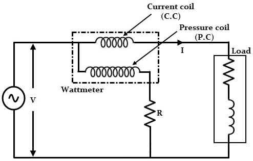
In order to measure the power, the load current must pass through the current coil (C.C) and hence it is connected in series with the load whereas the voltage across the load must appear across the pressure coil (P.C.) of the meter and hence it is connected across the load.
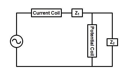
Now since the Potential coil is applied across the Z2. Hence the wattmeter reads power consumed by Z2.
Ques 3(c).A CRO Screen has 10 divisions on the horizontal scale. If a voltage signal 5 sin (314t + 45º) is examined with a line base setting of 5m sec/div, the number of cycle of the signal displayed on the screen will be?
Answer:-
Frequency is measured indirectly by measuring the period of the input signal. It is required that atleast one complete cycle of the waveform is displayed on the CRO screen. The numbs of divisions for one cycle of the waveform is read off from the screen of the CRO. Since th time/div setting on the front panel of the CRO gives the time/division of the horizontal seal in sec or ms or As the period of the waveform is given by
T = (time/div) x Number of divisions for one cycle
Voltage V = 5sin(314t + 45º)
Angular frequency (ω) = 314
ω = 2πf
f = 314/2π = 50 Hz
f = 1/T or T = 1/50 = 20 msec
Now, Line base setting = 5 ms/div, and total division present = 10
∴ Total time span = 5 ms/div × 10 div
= 50 msec.
Hence Number of cycle = 50 msec/20 msec = 2.5 cycle.
Ques 3(d). Prove that power in an AC circuit is equal to VIcosφ
Answer:-
In a DC circuit, the voltages and currents are generally constant, that is not varying with time as there is no sinusoidal waveform associated with the supply. Hence the power in DC circuit is simply the product of the DC voltage times the DC current, given in watts.
P = V.I
However, in an AC circuit, due to the presence of capacitor and Inductor the instantaneous values of the voltage, current and therefore power are constantly changing. So we can not calculate the power in AC circuits in the same way as we can in DC circuits.
Now consider a series RLC circuit in which the current leads the voltage by an angle φ.This condition occurs when the voltage across the capacitor is more than the voltage across the inductor.

Note:- We can also assume negative phase angle.
The Instantaneous voltage applied is given as
V = Vm sinωt
where Vm = is the maximum voltage or voltage amplitude
ω = angular frequency
I = Im sin(ωt + φ)
As in DC circuits, the instantaneous electric power in an AC circuit is given by P = VI
P = Vm sinωt × Im sin(ωt + φ)
P = VmIm sinωt . sin(ωt + φ)
Multiplying and dividing the above equation by 2 we get and as we know that
2sinA.sinB = cos(A − B) − cos(A + B)
[latex display=”true”]\begin{array}{l}P = \dfrac{{{V_m}{{\mathop{\rm I}\nolimits} _m}}}{2}2\sin \omega t.\sin (\omega t + \Phi )\\\\ = \dfrac{{{V_m}{{\mathop{\rm I}\nolimits} _m}}}{2}\left[ {\cos (\omega t – \omega t – \Phi ) – \cos (\omega t + \omega t + \Phi )} \right]\\\\ = \dfrac{{{V_m}{{\mathop{\rm I}\nolimits} _m}}}{2}\left[ {\cos \Phi – \cos (2\omega t + \Phi )} \right]\end{array}[/latex]
Now as we know that the average of all the instantaneous values of an alternating voltage and currents over one complete cycle is called Average Value. e.g sinωt, cosωt, cos2ωt , cos(2ωt + φ) etc.
If we consider symmetrical waves like sinusoidal current or voltage waveform, the positive half cycle will be exactly equal to negative half cycle.
Hence it is clear that the second terms of the above equation i.e cos(2ωt + φ) = 0
[latex display=”true”]\begin{array}{l}P = \dfrac{{{V_m}{{\mathop{\rm I}\nolimits} _m}}}{2}\left[ {\cos \Phi } \right]\\\\P = \dfrac{{{V_m}}}{{\sqrt 2 }}\dfrac{{{{\mathop{\rm I}\nolimits} _m}}}{{\sqrt 2 }}\left[ {\cos \Phi } \right]\\\\\dfrac{{{V_m}}}{{\sqrt 2 }} = {V_{RMS}}\\\\\dfrac{{{{\mathop{\rm I}\nolimits} _m}}}{{\sqrt 2 }} = {I_{RMS}}\\\\P = {V_{RMS}}{I_{RMS}}\cos \Phi \\\\or\\\\P = VI\cos \Phi \end{array}[/latex]