
Ques 4(a). Explain the various type of losses in DC machine.
Answer:- As we know that in DC machine, mechanical energy is converted into the electrical energy. During the process of conversion, the total input power is not transformed into output power. Some part of input power gets wasted in various forms.These losses give in the rise in temperature of the machine and reduce the efficiency of the machine.
For any dc. machine whether it is a generator or a motor, its efficiency is important It should work efficiently. This means that the losses must be as small as possible in d.c machines. The losses will determine the heating of the machine and hence the rating or power output that can be obtained without insulation failure. The various tests are performed to obtain the information about the various losses taking place in a d.c machine.
Losses in DC machine cause 2 main effect:-
- It increases the temperature inside the machine which affects the performance and life of the material of the machine, particularly insulation. Hence, the machine rating is directly affected by the losses.
- Ultimately, losses are waste of energy. In other words it is waste of money because these losses increase the operating cost of the machine.
However, losses cannot be eliminated completely. They can only be reduced to some acceptable level using proper design.
Losses in a D.C. Machine
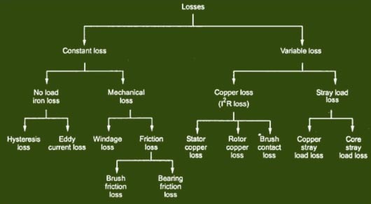
The various losses in a d.c. the machine, whether it is a motor or a generator, is categorized amplified into three groups as:
- Copper losses.
- Iron or core losses.
- Mechanical losses
- Stray Load Losses
Copper Losses
Copper losses are also called as Electrical losses, winding losses or Ohmic losses. The copper losses are the losses taking place due to the current flowing in a winding. There are basically two windings in a d.c. machine namely armature winding and field winding. The copper losses are proportional to the square of the current flowing Through these winding; Thus the various copper losses can be given by
- Armature copper losses (I2aRa)
- Shunt field winding losses (I2shRsh)
- Series field winding losses(I2seRse)
Core Losses
Core losses are also known as iron losses or Magnetic losses.These Losses are constant and Independent of the load. They are induced in the machine due to hysteresis and eddy currents produced in the core produced when the magnetization is changing. They mainly occur in the armature teeth and core as also in the pole shoe.
Hysteresis losses occur due to the reversal of the magnetization of armature core. So, the hysteresis loss can be obtained as:
Hysteresis Loss = Kh × BM1.67 × f × v watts
where
Kh = Hysteresis constant depends upon the material
Bm = Maximum flux density
f = frequency
v = Volume of the core
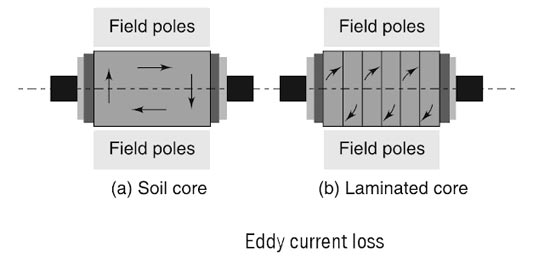
The eddy current loss exists due to eddy currents. When armature core rotates, it cuts the magnetic flux and e.m.f. gets induced in the core. This induced e.m.f. sets up eddy currents which cause the power loss. Ibis loss is given by,
Eddy current losses = Ke × Bm2 × f2 × t2
Where Ke = Eddy current constant
t = thickness of the core
Like other electrical currents, eddy currents are also influenced by the resistance of tl material in which the current is flowing. We know that the resistance of any material inversely proportional to its cross-sectional area. Figure (a) shows how eddy current induced in an armature core when the core is made of a solid piece of soft iron. Figure(b) shows a soft iron core of the same size as in the previous case but made up of a number of small pieces insulated from each other. This process is known as lamination. The current in each lamination is considerably lesser than that in the solid core because the resistance of the lamination is much higher due to the reason stated above, i.e., resistance is inversely proportional to cross-sectional area. The sum of the individual currents in all the laminations is also much lesser than that produced in the solid iron core.
Mechanical Losses
These losses are produced due to friction and windage (friction with air) caused by machine rotation. Hence, these are named as mechanical losses.Some power is required to overcome mechanical friction and wind resistance at the shaft.They depend on the speed of the machine. The mechanical losses are also constant for a d.c. machine
Bearing friction loss generally depends on the type of bearing used and on the viscosity of the lubricant.
Brush friction loss is proportional to the contact area and the brush pressure. It also depends on the other factors like material of the brush and commutator, their polish condition and the temperature at the contact surface.
Stray Load Losses
The magnetic and mechanical losses together are called stray losses. Stray load losses are losses that are produced in the machine when they are loaded. They cannot be considered with the main losses listed above. These losses include:
(a) Additional core loss resulting from armature reaction distortion.
(b) Copper loss due to short circuit produced in coils, segments, and brushes during commutation.
(c) Copper loss due to non-uniform distribution of current in large-sized armature conductors.
Stray load losses are very small in value and therefore, they are very difficult to calculate. In small machines, they can be neglected but for large machines, they are generally considered to be 1{ae7a908f8331c6c872d9d479ac609c519766cdb31fc9656c8a58125cc101951c} of the output power in total.
Constant and Variable Losses
For a DC Machine,
Total Losses = Constant losses + Variable losses
Constant losses are those losses which always occur irrespective of the load conditions and whose value remains constant for a given machine. Mechanical losses, core losses and shunt field copper losses are included in constant losses.
Variable losses are those losses which increase as the load on the machine is increased. They are electrical losses including armature copper losses, field winding copper losses, interpole winding copper losses, compensating winding copper losses and brush contact losses.
Copper losses increase proportionally to the square of the armature current while brush contact losses increase proportional to armature current. At full load, constant losses are 4{ae7a908f8331c6c872d9d479ac609c519766cdb31fc9656c8a58125cc101951c} to 20{ae7a908f8331c6c872d9d479ac609c519766cdb31fc9656c8a58125cc101951c} and variable losses are 3{ae7a908f8331c6c872d9d479ac609c519766cdb31fc9656c8a58125cc101951c} to 6{ae7a908f8331c6c872d9d479ac609c519766cdb31fc9656c8a58125cc101951c}.
Stray load losses do not have a fixed value. They are somehow related to armature current and speed. Since they are complicated to compute and are very small in value, they are mostly ignored.
Ques 4(b). A DC machine induces an EMF of 240V at 1500 rpm. Find the torque for an armature current of 25A.
Answer:- Derivation used in the Question
By the term, torque is meant the turning or twisting moment of a force about an axis. It is measured by the product of the force and the radius at which this force acts. Consider a pulley of radius r meter acted upon by a circumferential force of F Newton which causes it to rotate at N r.p.m.
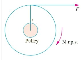
The angular speed of the pulley is
ω = 2πN/60 rad/sec
Work done by this force in one revolution
= Force × distance = F × 2πR Joule
The power developed = Work Done/Time
= (F × 2πR)/60/N
= (F × R) × (2πN)/60
The power developed = T × ω watt or P = T ω Watt
Armature Torque
Let Ta be the torque developed by the armature of a motor running at N r.p.s. If Ta is in N/M, then
power developed
P = Ta × 2π N watt
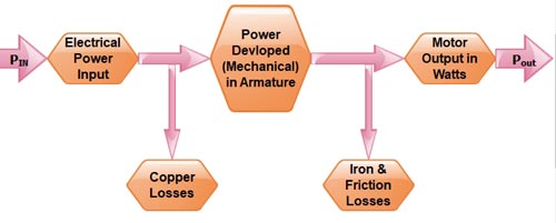
The electrical power converted into mechanical power in the armature = EbIa watt
Power in armature = Armature torque × ω
EbIa = Ta × 2πN/60
or
Ta = 9.55EbIa /N (N-m)
The back EMF (Eb) of the motor is given by
EB = PΦZN/60A
Φ = flux per pole in Weber
P = number of poles
Z = total number of armature conductor
N = rotation speed of the armature in revolution per minute (r.p.m)
A = number of parallel paths
[latex]\begin{array}{l}\dfrac{{P\Phi ZN}}{{60A}} \times {I_a} = {T_a} \times \dfrac{{2\pi N}}{{60}}\\\\{T_a} = \dfrac{1}{{2\pi }}\Phi {I_a} \times \dfrac{{PZ}}{A}\\\\{T_a} = 0.159\Phi {I_a}.\dfrac{{PZ}}{A}N – M\end{array}[/latex]
Shaft Torque ( Tsh )
The whole of the armature torque, as calculated above, is not available for doing useful work,
because a certain percentage of it is required for supplying iron and friction losses in the motor.
The torque which is available for doing useful work is known as shaft torque Tsh. It is so-called
because it is available at the shaft. The motor output is given by
Output = Tsh × 2πN Watt
Where Tsh is in N-m and
N in r.p.s.
[latex]\begin{array}{l}{T_{sh}} = \dfrac{{Output}}{{2\pi N}}{\text{N – m – N in r}}{\text{.p}}{\rm{.s}}\\\\ = \dfrac{{Output}}{{2\pi N/60}}{\text{N – m – N in r}}{\rm{.p}}{\rm{.m}}{\rm{.}}\\\\ = \dfrac{{60}}{{2\pi }}\dfrac{{Output}}{N}\\\\ = 9.55\dfrac{{Output}}{N}{\rm{N – m}}{\rm{.}}\end{array}[/latex]
Now As in the given question
Mechanical power developed in the armature = EbIa = 240 × 25A = 6000 W
Ta = 9.55EbIa/N
Ta = 9.55 × 6000/1500 = 38.2 N-m.
Ques 4(c). A 3300/300 V single phase transformer gives 0.6A and 60W as ammeter and wattmeter readings when supply is given to the low voltage windings and a high voltage winding is kept open. What is the power factor of no-load current?
Answer:-
Given
No load Losses = 60 W
No load Current = 0.6 A
As we Know that the Average power of an AC circuit is given as
Po = VIocosφ
60 = 300 × 0.6 × cosφ
cosφ = 60/180 = 0.33 Lagging
Hence power factor of No-load current is 0.33.
Ques 4(d). A 3 H.P, 3 Phase 4 Pole, 400 V, 50 Hz induction motor runs at 1440 RPM. What will be the frequency of Rotor induced EMF?
Answer:-
Given
Stator Frequency f = 50Hz
Number of poles P = 4
Rotor Speed Nr = 1440 RPM
Rotor frequency =?
The Synchronous speed of induction Motor is given as
Ns = 120f/P = 120 × 50/4 = 1500 RPM
The Slip of an Induction motor is given as
s= Ns – N / Ns.
1500 – 1440 / 1500 = 60 / 1500
Now frequency induced e.m.f in rotor (fr) = sf
∴(fr) = 60 / 1500 × 50 = 2 Hz.
Hence Rotor frequency is 2 Hz.