
Ques 5(a). Explain the need for connecting a capacitor in the auxiliary winding of a single phase Induction Motor?
Answer:-
There are probably more single-phase motors in use today than the total of all the other types put together. It is the least expensive and requires the least maintenance. They operate from a single-phase supply, and they find numerous applications in homes, offices, and industry. The technological advances in design have made it possible for these motors to be used in space vehicles, aviation industry, power tools and business establishments. These motors are manufactured in fractional horsepower ratings.
The working principle of an ac machine is primarily “one field following another field”. In the case of a multiphase induction motor, there will be a virtual rotating magnetic field. But considering the case of a single phase induction motor, it’s only a pulsating field that is produced and not a rotating one. This can also be explained on the basis of ‘DOUBLE REVOLVING FIELD THEORY‘, which is based on Ferraris Principle
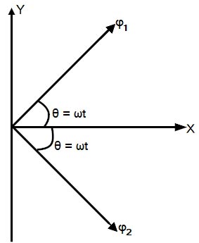
As per Ferrari’s principle, the alternating magnetic field produced by the stator can be split into two rotating magnetic fields of half the magnitude and rotating at the synchronous speed in opposite directions. When the alternating supply is fed to the stator winding, an alternating flux is developed This flux rotates and cuts the rotor conductors. Due to this, an EMF is induced. As the rotor circuit is closed the current flows through the rotor conductor. This rotor current will cause rotor flux.and at any instant, its magnitude is given by,
φs = φm COS ωt
where φm is the maximum flux developed in the motor. According to this theory, the alternating flux φs can be resolved into two components of and φf & φb such that the magnitude of by φf & φb is equal to half the magnitude of φs . Let us assume that φf rotates in clockwise direction and φb rotates in the anti-clockwise direction.
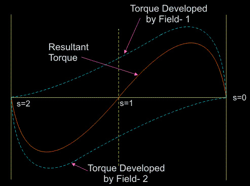
An emf is induced in the rotor circuit due to each rotating field. If the polarity of the induced emf in the rotor due to φf is taken as positive then emf induced in the rotor due to φb is negative (i.e. in phase opposition). As, at standstill, the slip in either direction is same (i.e. s = 1), the rotor impedance will also be same. Thus, the rotor currents are equal, but opposite in phase that is the starting torque developed by each revolving field is the same, with one acting in forwarding direction and other acting in the backward direction. Thus, the net torque developed by the motor is zero.
Based on double revolving field theory, a single phase induction motor can be visualized as having two rotors revolving in opposite directions with a common stator winding. At standstill, the two rotors develop equal torques in opposite directions and hence the net torque developed is zero.
Starting Method of Single-phase Induction Motor
It is observed that with only main field energized, the single-phase induction motor will not start. However, if an external torque moves the motor in any direction, the motor will begin to rotate. The absence of rotating magnetic field is due to only one winding, in order to produce rotating magnetic field, the motor should have at least two windings with currents which differ in phase. So what is needed is a second (auxiliary) winding, with currents out of phase with the original (main) winding, to produce a net rotating magnetic field. The various single-phase motor designs differ in the type of secondary (auxiliary) winding employed and method of achieving time phase difference between the currents in main winding and starting winding. These starting windings, together with other components such as capacitors, relays and centrifugal switches make up the starting circuit and provide varying effects on motor starting and running characteristics. Following techniques are used for starting single-phase induction motors:.
- Split Phase or Resistance Start
- Capacitor Start
- Permanent Split Capacitor
- Capacitor Start-Capacitor Run
- Shaded Pole
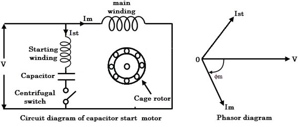
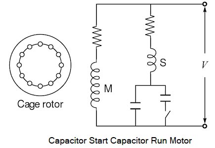
Capacitor Start Motor
- In a capacitor start the motor, the running winding is inductive in nature so, the current flowing in running winding lags behind applied voltage by an angle, φm.
- The idea behind capacitor start single phase motors is an extension of the split phase winding technique used to produce the starting torque in single phase induction motor.
- In capacitor start induction motor a capacitor is placed in series with the auxiliary winding of the motor. By proper selection of capacitor size, the magnetomotive force of the starting current in the auxiliary winding can be adjusted to be equal to the magnetomotive force of the current in the main winding.
- Now as we know that in the capacitor the current leads the voltage by90 degrees.
- Therefore the value of the capacitor is so chosen that the current Is in the auxiliary coil leads current Im in the main coil by about 80° (i.e., α ~ 80°) which is considerably greater than 25° found in split phase motor.
- This becomes a balanced 2 phase motor if the magnitude of Is and Im are equal and are displaced in time phase by 90° electrical degrees.
- Now there occur large phase angle differences between these two currents which produce a resultant current, I and this will produce a rotating magnetic field.
- The starting winding is opened by the centrifugal switch when the motor attains about 75{ae7a908f8331c6c872d9d479ac609c519766cdb31fc9656c8a58125cc101951c} of synchronous speed. The motor then operates as a single-phase induction motor and continues to accelerate till it reaches the normal speed.
There are three main types of the capacitor motor
- Capacitor start induction run motor: The capacitor (or starting) winding remains energized during the starting period only.
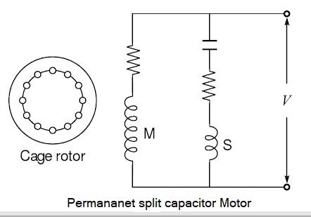
- Permanent split capacitor motor: The capacitor (or starting) winding works both for starting and running periods. The schematic diagram is shown in Fig.
3. Capacitor start and capacitor run motor: Two capacitors are used for starting, but one of them is cut out when speed reaches 70 percent of the synchronous speed. The schematic diagram is shown in Fig.
For starting purpose a high capacitor is needed. A paper capacitor of this capacitor is bulky and costly. Hence, it is not Vise to use this type of capacitor. A dry type electrolytic capacitor of high capacity is available in small sizes and at cheaper rates. However, this type of capacitor is short time rated for ac working and hence cannot be used for capacitor run motors but can be used for starting. The normal running torque required is lower than the starting torque. Hence, a smaller capacitor is required for running than for starting. So, for running paper capacitor can be used. As the voltage across the capacitor can be higher than the main voltage, the capacitor voltage rating must be high. For example, 275 V rating for 200-250 V motors.
In general, the capacitor motors are used when high starting torque is the need. A capacitor starts induction run motor uses electrolytic type capacitor of high capacity and develops high starting torque. This type of motor can, therefore, be started against the high load. For example, these motors can be used for driving refrigerator compressors.
A permanent split capacitor motor uses a paper capacitor of small capacity and hence, its starting torque ranges between that of the capacitor start motors and split phase motors. These motors, in small sizes, are useful where light starting torque is required, such as electric fans. Another advantage of this type of motors is the improved power factor as there is a capacitor in the circuit while running.
Capacitor start and run motors have the properties of both capacitors start motors and permanent capacitor motors. So, this type of motors can be used when the starting torque required is high and it is desired to achieve a high power factor while running. The starting capacitor used is of electrolytic type and that used for running is of paper type.
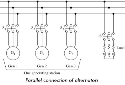
Ques 5(b):- Why are two alternators connected in parallel to supply a common load? What are the necessary conditions for parallel connection?
Answer:- The demand for power is increasing day by day. It is a challenge for power engineers to meet the power demand of customers. A single alternator cannot meet the power demand. To meet the excess power demand, additional alternators are connected in parallel. If a single alternator can meet the power demand, an outage of the alternator will cause an interruption of power supply. On the other hand, paralleling of alternators ensures the supply of a part of the total demand when one alternator is out of order.
- A single alternator may not meet the local or regional power requirements.
- It is possible to shut down one or more alternators for scheduled or emergency maintenance when the alternators are operating in parallel. The load can be supplied.
- At part load, one or more alternators are shut down and the remaining load is carried out with few machines efficiently because alternators are inefficient at part load.
- It is possible to handle load growth by adding alternators without disturbing the original installation.
- The available machine prime movers and alternators can be matched to obtain economical cost and reliable use.
Condition for parallel Operation of an alternator
The following condition must be satisfied for parallel operation of an alternator
- Same Voltage Ratio
- Same Phase Sequence
- Same Frequency
Same Voltage Ratio:-
The voltages must be the same as the paralleling point or junction even though not the same at the alternators. During paralleling of two alternators, the voltages at the paralleling point must be the same. Any mismatch of the paralleling point voltage will cause the circulating current to flow between them. This will cause sufficient voltage drops through the armature resistance. This circulating current causes the I2R loss through the armature winding resistance, which results in heating of the generators and hence additional load on the prime movers. Therefore, this mismatch should be avoided.
Identical Phase Sequence
- The phase of the incoming machine must be identical to that of the bus. If the bus has phase sequence A-B-C, the incoming machine must have phase sequence. If the incoming machine has the phase sequence A-C-B, it will cause a disastrous short circuit.
- If the phase sequence A of the incoming machine and the bus is fully synchronized and phase sequences B and C of the incoming machine mate with the phase sequences C and B of the bus respectively, this mismatch between two phase sequences out of three phase sequences will result in short-circuit current, which is ultimately limited by the combined synchronous impedances of the windings involved.
- This short-circuit current will be even more at the moment of switch closure. This is because the armature reaction cross-magnetization needs time to be established. This out of phase sequence should be avoided very carefully.
Same Frequency Requirement
The frequency of the incoming machine must be identical to the frequency of the bus. If the frequency difference is very small and the alternator is in phase with the bus, the paralleling condition will be successful.
Relation of Prime Mover Torque Speed
The prime movers of the alternators must have drooping and similar speed-torque characteristic for perfect load sharing. Rising speed-torque characteristic must be avoided.
Advantage of Parallel Operation of Synchronous Generators
The following are the advantages of connecting a large number of synchronous generators in parallel to supply a common load:
- Continuity of Supply and Maintenance: Repair and maintenance of individual generating units can be done keeping the continuity of supply by properly scheduling maintenance of generators one after the other. If only one large generator is installed, supply is to be cut off for maintenance work.
- Efficiency: For operating an alternator on maximum efficiency it is to be run near to its full-load capacity. It is uneconomic to operate large alternators on low loads. If several small units are used. units can be added or put off depending upon the load requirement and thus the units can be operated at near to their rated capacity.
- Capital Cost: Additional sets can be connected in parallel to meet the increasing demand, thereby reducing the initial capital cost of buying larger units in anticipation of increasing demands.
- Size of Alternators: There is the physical and economic limit to the possible capacity of alternators that can be built. The demand for a single power station may be as high as 1200 MVA. It may not be feasible to build a single alternator of such a high rating due to physical and economic considerations.
Ques 5(c). What are the advantages and disadvantages of AC over DC?
Answer 5(c). Generation, Transmission, and Distribution systems are the main components of an electric power system. Generating stations and distribution systems are connected through transmission lines. Normally, transmission lines imply the bulk transfer of power by high-voltage links between main load centers. On the other hand, the distribution system is mainly responsible for the conveyance of this power to the consumers by means of lower voltage networks. Electric power is generated in the range of 11 kV to 25 kV, which is increased by stepped-up transformers to the main transmission voltage.
Electric Power can either be transmitted by means of AC or DC. Each system has their advantages and disadvantages. Therefore it is very crucial to have a comparative study of their merit and demerits and then decide which method should be adapted to transmit power.
ALTERNATING CURRENT (A.C.)
An alternating current is one which periodically changes in magnitude and direction. It increases from zero to a maximum value, then decreases to zero and reverses in direction, increases to a maximum in this direction, and then decreases to zero. The complete set of variations is known as a ‘cycle’. Thus during one-half of the cycle, the current flows in one direction, and in the following Cycle, it flows in the opposite direction.
DIRECT CURRENT (D.C.)
Dhect current is that current which may or may not change in magnitude but it does not change its direction.
A.C. VERSUS D.C.
It is worthwhile to give advantages of ac. and d.c. Advantages of a.c. over d.c.
ADVANTAGES OF A.C OVER DC
- Alternating voltages can be stepped up or stepped down efficiently by a transformer. This permits the transmission of electric power at high voltages to achieve economy and distribute the power at utilization voltages.
- A.C. motors are cheaper and simpler in construction than the d.c. motors.
- The switchgear (e.g. switches, circuit breakers, etc.) for a.c. the system is cheaper than the d.c. system.
- Alternating currents can be controlled with a choke coil without any appreciable loss of electrical energy.
- A.C. can be easily converted into d.c. by rectifiers.
- Alternating current can be regulated by using a choke coil without any significant wastage of electrical energy.
- Alternating voltage can be Transmitted to distant places with very little loss in A.C. power.
- We all know that we got A.C supply in our homes and we got this supply by transmitting ac over long distances. AC can be transmitted using step-up transformers but direct current or dc cannot be transmitted by this method.
- The maintenance of a.c. sub-stations is easy and cheaper.
- The wide range of voltage can be obtained by using the step-up or step-down transformer.
- A.C. can be produced and transmitted easily and cheaply than D.C.
- A 3-phase A.C. Dynamo can produce more energy than a single phase D.C. Dynamo of the same cost. A.C.
- Dynamo (using slip rings) has less loss of energy and wear and tear than a D.C. Dynamo (using split ring commutator).
- Transmission of A.C. at ‘high-voltage’ and ‘low-voltage‘ reduces line losses.
DISADVANTAGES OF AC OVER DC
- A.C. is transmitted more over the surface of the conductor than from inside. This is called skin effect. To avoid skin effect, a.c. is transmitted over several fine insulated wires instead of a single thick wire.
- The peak value of AC is high and it is dangerous to use so better insulation is required.
- AC causes more Interference with the nearby communication line.
- In A.C transmission the voltage regulation is poor than that of DC transmission.
- An AC transmission line cannot change rapidly in magnitude and direction of power flow as DC line.
- A.C. cannot be used For some processes, e.g. electroplating, charging of batteries, etc.
- The construction of AC transmission line is more complicated as compared to DC transmission line.
- The shock of a.c. is attractive whereas that of d.c. is repulsive.
- For the same value of voltage, ac. is more dangerous than d.c.AC gives huge and sudden shock which can be very dangerous.
- The leakage in AC transmission line is more than the DC transmission line, therefore, better insulation is required.
Ques 5 (d):- Why overhead transmission line is preferred over underground power cables?
Answer:- Electric Power needs to be carried over long distances from the point of generation to the point of consumption.
Electric power systems are composed of many complex components, designed to operate together to safely provide quality and reliable electricity to the consumers. The main components are: Power generation plants, overhead lines, underground cables and substations including transformers, switch gears and several auxiliary, safety and protection systems.
Types of Transmission
In general two types of systems are used for the transmission.
- Overhead system
- Underground system
Overhead System
Overhead transmission lines are the highways to transport electric energy within power supply systems.
Overhead lines are the most common system for power transport outside of residential areas. They are available for all voltage levels from 0.4 kV up to 1000 kV. In this system, the transmission of electrical power is by wing overhead transmission lines over long distances. In such system, the appropriate spacing is provided between the conductors, at the supports as well as at the intermediate points. This spacing provides insulations which avoids an electric discharge to occur between the conductor.
Underground System
Underground cables are generally not used at the transmission level unless the situation demands. Of course, at distribution levels, these are used in areas where the population density is high. However, the length of the cable will generally be small. The main concern in cables is the insulation to be provided between conductors and between conductors to earth due to the reason that the spacing between the conductors will be much less compared to that in case of overhead lines. The cables are generally preferred in the underground system. All the conductors must be insulated from each other in the underground system.
Underground power cables are widely used in transmission and distribution of electrical power, the following are the advantages of underground power cables compared with the overhead transmission lines feeders.
Advantages of Overhead Transmission Line
- Initial cost: -The underground system is more expensive due to the high cost of trenching, conduits, cables, manholes and other special equipment. The initial cost of an underground system may be five to ten times than that of an overhead system.
- Flexibility:- The overhead system is much more flexible than the underground system. In the latter case, manholes, duct lines etc., are permanently placed once installed and the load expansion can only be met by laying new lines. However, on an overhead system, poles, wires, transformers etc., can be easily shifted to meet the changes in load conditions.
- Fault location and repairs:- On an overhead system, the conductors are visible and easily accessible so that fault locations and repairs can be easily made.There are little chances of faults in an underground system. However, if a fault does occur, it is difficult to locate and repair on this system.
- Current carrying capacity and voltage drop:- An overhead conductor has a considerably higher current carrying capacity than an underground cable conductor of the same material and cross-section. On the other hand, underground cable conductor has much lower inductive reactance than that of an overhead conductor because of closer spacing of conductors.
- The annual cost of operation: It is the most powerful factor influencing the choice between underground and overhead system. The greater capital cost of underground system prohibits its use for distribution.
- Size of conductor:- In an overhead transmission line, the size of the conductor for the same amount of power is small but in case of an underground cable size of the conductor is large.
- Heat Dissipation:- Heat can be dissipated easily in an overhead transmission line as they are open to atmosphere and in case of the underground cable heat dissipation is too much difficult hence the number of the insulation layer is larger.
- Line modifications:- Extension or joining on overhead lines can be performed easily and also it facilitates easy replacing. Overhead power lines are easily tapped, rerouted or modified to serve customers; underground lines are more difficult to modify after the cables have been installed. Such modifications to underground power lines are more expensive because of the inability to readily access lines or relocate sections of lines.
Disadvantages of Overhead Transmission Line
- Public safety:- The underground system is safer than overhead system because all distribution wiring is placed underground and there are little chances of any hazard.
- Faults:- The chances of faults in the underground system are very rare as the cables are laid underground and are generally provided with better insulation.
- Appearance:- The general appearance of an underground system is better as all the distribution lines are invisible. This factor is exerting considerable public pressure on electric supply companies to switch over to the underground system.
- Useful life:- The useful life of the underground system is much longer than that of an overhead system. An overhead system may have a useful life of 25 years, whereas an underground system may have a useful life of more than 50 years.
- Maintenance cost:- The maintenance cost of the underground system is very low as compared with that of an overhead system because of fewer chances of faults and service interruptions from wind, ice, lightning as well as from traffic hazards.
- Interference with communication circuits:- An overhead system causes electromagnetic interference with the telephone lines. The power line currents are superimposed on speech currents, resulting in the potential of the communication channel being raised to an undesirable level. However, there is no such interference with the underground system.
Ques 5(d). What are the main advantages of SF6 Circuit Breakers?
Answer:- Circuit breakers are the mechanical device designed to close or open contacts members, thus closing or opening of an electrical circuit under normal or abnormal conditions.
Circuit breakers are made in varying sizes, from small devices that protect low-current circuits or individual household appliance, up to large switchgear designed to protect high voltage circuits feeding an entire city.
Types of Circuit Breakers
The different types of high voltage circuit breakers which include the following
- Air Break Circuit Breaker
- SF6 Circuit Breaker
- Vacuum Circuit Breaker
- Oil Circuit Breaker
- Air blast circuit Breaker
SF6 gas circuit breakers are widely used for EHV applications today, as Sulphur hexafluoride(SF6) gas is an electronegative gas having excellent di-electric and arc quenching properties resulting in many advantages such as compactness and less maintenance of EHV circuit breaker
The excellent insulating properties of SF6 gas make it possible to design circuit breakers with smaller overall dimensions, shorter contact gaps, which help in the construction of outdoor breakers with fewer interrupters, and evolution of metal enclosed SF6 gas insulated switchgear.
Advantages of SF6 Circuit Breaker
- Non-inflammable: The gas is non-inflammable and chemically stable. The decomposition products are non-explosive i.e, there is no risk of fire or explosion
- Insulating: SF6 gas provides Excellent insulating, arc extinguishing, physical and chemical properties.
- Atmospheric Condition: Its performance is not affected due to variation in atmospheric conditions.
- Clearance: Electrical clearances are very much reduced because of the high dielectric strength of SF6.
- Noiseless Operation: It gives noiseless operation it does not make the sound like air-blast circuit breaker during operation
- No overvoltage problem. The arc is extinguished at natural current zero without the current chopping and associated over-voltages originating across the circuit breaker terminals
- Low Contamination: The sealed construction avoids the contamination by moisture, dust, sand etc. No costly compressed air system is required as in the case of air blast circuit breaker
- Multipurpose: The SF6 gas circuit breaker can perform various duties like clearing short-line faults, opening unloaded transmission lines, capacitor switching, transformer reactor switching etc without any problem
- Excellent Dielectric: Since no carbon particle is formed during the arcing therefore there is no reduction in dielectric strength of SF6 circuit breaker.
- Minimum maintenance: The breaker may require maintenance once in four to ten years
- Outdoor EHV SF6 circuit breaker has less number of interrupters per pole in comparison to the air-blast circuit breaker and minimum oil breaker. The outdoor SF6 circuit breaker is simple, comparatively cheaper in cost, maintenance free and compact
- Ample overload margin. For the same size of the conductors, the current carrying capacity of the SF6 circuit breakers is about 1.5 times that of the air blast circuit breakers because of superior heat transfer capability of the SF6 gas
- Low gas Required: Same gas is re-circulated into the circuit thereby reducing the requirement of SF6 gas.
- No oxidation: No frequent contact replacement-arcing time is small owing to outstanding arc quenching properties of SF6 and therefore contact erosion is less. Hence contacts do not suffer oxidation
Disadvantages of SF6 Circuit Breaker:
- Imperfect joints leading to leakage of the SF6 gas. Continuous monitoring devices are required
- SF6 gas is suffocating to some extent. In case of leakage in the breaker tank SF6 gas being heavier than the air settles in the surroundings and may lead to suffocation of the operating personnel. However, it is not poisonous
- Arced SF6 gas is poisonous and should not be inhaled
- The internal parts need thorough cleaning during periodic maintenance under clean and dry environment. Dust of Teflon and sulfides should be removed
- Special facilities are required for transportation of gas, transfer of gas an maintenance of quality of the gas. The deterioration of the quality of gas affects the performance and hence reliability of the SF6 circuit breaker.