
Ques 3a:- Prove that the reactive power in A.C circuit is equal to VI sin Φ
Sol- Reactive power is the electrical power that oscillates between the magnetic field of an inductor and the electric field of the capacitor. Reactive Power Cannot Converts to non-electrical power e.g. heat, light & torque.
Reactive power is also referred as an imaginary power.Reactive power is the useful concept in power system because the system voltage is affected by the reactive power. The reactive power taken by an inductor is positive while the reactive power taken by the capacitor is negative.
Proving:
We know that the average power or real power dissipated is
Pavg = VI CosΦ———(1)
The power triangle or Impedance triangle of the AC circuit is shown Below
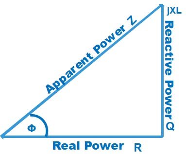
[latex display=”true”]Cos\Phi = \dfrac{{Base}}{{{\rm{Hypotenuse}}}} = \dfrac{{True{\text{ Power}}}}{{Apparent{\text{ Power}}}} = \dfrac{R}{Z}[/latex]
By Ohm’s Law the impedance of the circuit is given as
Z = V/I
V = IZ
Putting the value of cosΦ and V in equation 1
[latex]{P_{avg}} = IZ\left( {I\dfrac{R}{Z}} \right) = {I^2}R\ watt[/latex]
The above equation indicate the average power dissipated in a resistive circuit.
Now let us assume a circuit consisting of a pure inductor, then the power in the inductor is given as
P = IVL
= IL(di/dt)
Where I = Im sin(ωt + Φ)
then
P = I2m sin(ωt + Φ) Lω Cos(ωt + Φ)
P = I2 ωLsin2(ωt + Φ)
From the above equation, we can say that the average power delivered to the circuit is zero. This is called reactive power. It is expressed in volt-amperes reactive (VAR).
P = I2XL VAR ————2
From Impedance figure
SinΦ = XL/Z = XL = ZsinΦ
Putting the value of XL in equation 2
P = I2 ZsinΦ
P = (IZ) IsinΦ
P = V I SinΦ
Ques 3(b): A 50 µA meter movement with an internal resistance of 1 kΩ is to be used as a dc voltmeter of range 50 V. Calculate the
(i) multiplier resistance required, and
(ii) voltage multiplying factor.
Sol 3. Given
i = 50 µ A
Rm (Meter Resistance) = 1 KΩ
Rse (Controlling Resistance) = ?
(i) Controlling Resistance can be derived as
(Rm + Rse) = Total Resistance = (Sensitivity × Range)
Rse = ( S × Range) – Rm
Sensitivity = 1/Ampere = 1/50 = 20KΩ/V
Rse = 20 × 50 – 1 = 999KΩ
(ii) Voltage Multiplying Factor (m)
[latex]m = \dfrac{{{V_{range}}}}{{{V_m}}} = \dfrac{{{V_{range}}}}{{{I_m}{R_m}}} = \dfrac{{50}}{{50 \times {{10}^{ – 6}} \times 1K}} = 1000[/latex]
Ques 3(c): In a gravity controlled instrument, the controlling weight is 0.005 kg and acts at a distance of 2.4 cm from the axis of the moving system. Determine the deflection in degrees corresponding to deflecting torque of 1.05 × 10⁻⁵ kgm.
Sol: For the steady-state deflection angle θ, we have
Deflecting Torque Td = Controlling Torque Tc
Td = Wl sinθ
[latex]\theta = {\sin ^{ – 1}}\dfrac{{{\tau _d}}}{{Wl}} = {\sin ^{ – 1}}\dfrac{{1.05 \times {{10}^{ – 5}}}}{{0.005 \times 0.024}} = 61.04^\circ[/latex]
Ques 3 (d):- Explain in brief
(i) Megger
(ii) Two-wattmeter method
(iii) Signal generator
(iv) Earth fault detection
(v) AC bridge
Megger:-
Insulation testing megger is a portable instrument used for testing the insulation resistance of a circuit, and for measuring the resistance of the order of megaohms in which the measured value of resistance is directly indicated on a scale.
Principle: The instrument works on the principle of ratiometer/ohmmeter. The required deflecting torque is produced by both the system voltage and the current Due to interaction between the magnetic fields produced by the voltage and the current, the deflecting torque is produced. The required coils are so positioned that the deflecting torque is proportional to the ratio, VI.
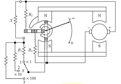
The control coil moves over the annular core while the compensating coil moves over the extension of the pole piece of the permanent magnet. The torque produced by the current coil opposes the torque produced by the voltage coils. The current coil in series with a resistance R1 and the unknown resistance X is connected across the supply. Thus the current through the current coil is same as that through the unknown resistance X. The two voltage coils in series are connected, in series with resistances R2 and R3, across the supply. Thus, the current through the voltage coils is proportional to the volt drop across the current coil.
Working
When the current flows from the generator, through the pressure coil the coil tends to set itself at right angles to the field of the permanent magnet.The speed of the generator is between 140 – 180 RPM.
When the test terminals are open, corresponding to infinite resistance, no current flows through deflection coil. Thus the pressure coil governs the motion of the moving element making it move to its extreme anticlockwise position. The pointer comes to rest at the infinity end of the scale.
When the test terminals are short-circuited i.e. corresponding to zero resistance, the current from the generator flowing through the current coil is large enough to produce sufficient torque to overcome the counter-clockwise torque of the pressure coil. due to this, the pointer moves over a scale showing zero resistance.
When the high resistance to be tested is connected between terminals T1 and T2 the opposing torques of the coils balance each other so that pointer attains a stationary position at some intermediate point on the scale. The scale is calibrated in megaohms so that the resistance is directly indicated by the pointer.The guard ring is provided to eliminate the error due to leakage current. Meggar speed is kept as steady as possible because a small change in the speed of the megger would change the charging current and give a false reading of insulation resistance. The speed of megger is kept between 140 -160 RPM.
Note: if you don’t have sufficient time try to explain the question pointwise
Construction: It consists of
- A small hand driven d.c. generator
- A moving element which has 2 coils, a deflecting coil (or current coil) and a controlling coil (or potential coil).
- Calibrated scale in mega ohms
- Pointer
- Permanent magnet.
Working
- The hand driven generator is of permanent magnet type and it is designed to generate from 500 to 2500 volts.The speed of megger is kept between 140 -160 RPM.
- Resistance to be measured is connected across the test terminals, i.e. connected in series with the deflecting coil and across the generator. When currents are supplied to the coils, then they have torques in opposite directions.
- If the resistance to be measured is high, no current will flow through the deflecting coil. The controlling coil will, therefore, set itself perpendicular to the magnetic axis and hence, sets the pointer at infinity.
- If the resistance to be measured is small, a high current flows through the deflecting coil and the resulting torques set the pointer to zero.
- For intermediate values of resistance, depending upon the torque production, the pointer is set at a point between zero and infinity.
Advantages of Meggar
- It is easily portable.
- There is no external supply is required for a practical meggar because the hand driven generator produces the requires voltage source for the current coil and potential coil.
- Widely used as “Insulation tester” as the insulation resistance are quite high.
Application of Meggar
- It is used for the measurement of insulation resistance of cable, transformer, bushing insulation and winding insulation of electrical motors, generators, and transformers.
- The megger can also be used to test continuity between any two points. When connected to the two points, if pointer shows full deflection then there is an electrical continuity between them.
- Meggers are used in industries for observing the following tests:—-
- Open-circuit tests
- Short-circuit tests
- Continuity tests
- Ground tests
- Earth resistance tests
Two-wattmeter method :
Power in a 3-phase three wire system, with balanced or unbalanced load, can be measured by using two wattmeters. The load may be star or delta connected. The current coils of the two wattmeters are connected in any of the two lines and the pressure coils are connected between these lines and the third line, as shown in Fig. The two-wattmeter method can be explained somewhat more clearly by considering a balanced load. In this case, we shall prove that power measured by the two wattmeters (i.e., the sum of two wattmeter readings) is equal to the total power consumed in three-phase balanced load.
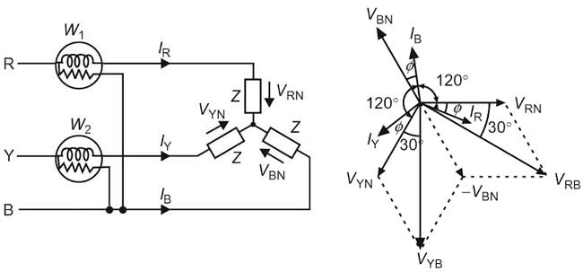
The connection diagram for a three-phase balanced load (connected in the star). Considering load to be an inductive one.The three voltages VRN, VYN, and VBN, are displaced by an angle of 120 degrees electrical as shown in the phasor diagram. The phase currents lag behind their respective phase voltages by an angle ϕ.
Let VRN, VYN, and VBN be the voltages across three phase of the load and IR, IY, IB is the current flowing in the three lines.
Total Instantaneous power in the load = VRN IR + VYN IY + VBN IB—————(1)
Instantaneous current through the current coil of Wattmeter W1 = IR
Instantaneous current across the pressure coil of Wattmeter W1 = VRB = VRN – VBN
Instantaneous power measured by the Wattmeter W1 = IR × (VRN – VBN) = IR × VRB
Instantaneous current through the current coil of Wattmeter W2 = IY
Instantaneous current across the pressure coil of Wattmeter W2 = VYB = VYN – VBN
Instantaneous power measured by the Wattmeter W2 = IY × (VYN – VBN) = IR × VYB
For three phase, Three wire system IR + IY + IB = 0
∴ IB = −(IR + IY)
Substituting the value of in IB equation 1
Total Instantaneous power in the load = VRN IR + VYN IY + VBN (−IR − IY)
= IR(VRN − VBN) + IY(VYN − VBN)
= Power measured by the Wattmeter W1 + Power measured by the Wattmeter W2
Advantage of Two wattmeter Method
- The method is applicable for balanced as well as unbalanced load
- Neutral point for star connected load is not necessary to connect the wattmeter.
- The delta connected load, need not be opened for connecting the wattmeters.
- Only two wattmeters are sufficient for measuring the total 3 phase power.
- Total reactive volt-amperes can be obtained using the two wattmeters reading for balanced loads.
Disadvantages of two wattmeter method
- The sign of both the wattmeter must be identified and noted correctly otherwise it may lead to the wrong result.
- Two wattmeter method is not applicable for Three-phase, four wire system.
Signal Generator:
Generation of signals is an important aspect in electronic circuits and troubleshooting. Signal generators have a variety of applications, such as checking the stage gain, frequency response, and alignment in receivers and in a wide range of other electronic equipment.The signal generator provides an excitation to the electronic measurement systems and processing circuits which convert various transducer outputs into useful data. The excitation provided by signal generator may be a constant d.c voltage or current or even stable a.c signal. There are various types of signal generators:
- Standard signal generator: This instrument produces sinusoidal waveforms in audit frequency (AF) and radio frequency (RF) ranges. Continuous wave and modulated RF signals can also be produced. This is an oscillator with a modulation capability. Signal Generator provides several output waveforms, including sine wave, square wave, triangular wave and pulse trains, as well as an amplitude modulated waveform.
- Oscillators: The term oscillator is used to describe an instrument that provides only a sinusoidal output signal. These are available in the AF and RF ranges separately with variable amplitude and frequency. Modulated signals will not be available.Hence, when we say that the oscillator generates a signal, it is important to note that no energy is created; it is simply converted from a dc source into ac energy at some specific frequency.
- Test oscillator: It is also an oscillator circuit with a calibrated attenuator and an output monitor.
- Function Generator: Function Generator provides several output waveforms, including sine wave, square wave, triangular wave and pulse trains, as well as an amplitude modulated waveform.In this instrument, it sine wave is synthesized. Distortion will be more in the sine wave compared to that produced in oscillator instruments.
- Sweep generator: It generates Ramp waveforms with variable slopes.
- Pulse Generator: Pulse generator produces Rectangular waveforms with variable duty cycles, variable frequency and amplitude.
Signal sources can be broadly classified as follows:
- Fixed.
- Variable.
- In the fixed signal generators, the amplitude of the waveform or the Frequency or both may be fixed. But such instruments have limited applications.
- In the variable type, the amplitude of the waveform can be varied from ‘mv’ to ‘volts’. The frequency is also variable over a wide range.
Features of Signal Generators:
The desirable features of signal generators.
- A signal generator must be capable of producing stable signals over a wide range of Frequencies from few to GHz range.
- The amplitude must also be variable from a low-value to high value and attenuators are usually provided to change the amplitude.
- The signal generated by the instrument must be free from distortion.
- Amplitude and frequency stability with variation in temperature muse be good.
- The harmonic contents in the output should be as low as possible.
- The signal generator should provide the very low spurious output; that means the effect of hum, noise, jitter, and modulation should be negligible.
Block Diagram of Singal Generator
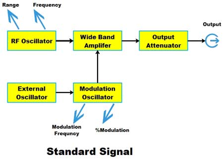
A standard signal generator produces known and controllable voltages. It is used as power source for the measurement of gain, signal to noise ratio, bandwidth, standing wave ratio and other properties. It is extensively used in the testing of radio receivers and transmitters.
The instrument is provided with a means of modulating the carrier frequency. The modulation is indicated by a meter. The output signal can be Amplitude Modulated (AM) or Frequency Modulated (FM). Modulation may be done by a sine wave, square wave. triangular wave or a Pulse.
A signal generator consists of two important main blocks
- Oscillator
- Attenuator
- The oscillator uses an active device such as an operational amplifier. The output of an operational amplifier is fed back in phase with the input. This positive feedback causes regenerative action resulting in an oscillation.
- The attenuator provides amplitude control. Basically, the attenuator is a device which reduces or attenuates the power level of the signal by the fixed amount.
The proper functioning of a signal generator depends on the performance of an oscillator and attenuator.
Earth fault detection :
The flow of electrical power from the generating station to the consumer is called an electrical power system or electrical supply system. it consists of the following important components :
- Generation
- Transmission network
- Distribution network
The purpose of the medium voltage network is to distribute electrical power from the high voltage transmission stage to the decentralized customers. In today’s world, the power sources are more distributed, with a significant and increasing number of the energy sources connected to the distribution network, the protection of these networks has become more complex. Since cables are predominant in medium voltage networks, the capacitance is large. These networks are operated with compensated or isolated star-point grounding, depending on the level of capacitive current.Since the single pole to ground fault introduces severe asymmetry in the voltages (e.g. magnitudes of two unaffected phases are significantly higher), the fault location needs to be detected in order to restore the system to normal operation.
Compensated Star Point
In this case, cable capacities of the entire network system are largely compensated through the inductance of a Petersen earth fault neutralizer. In case of an earth fault, the residual currents still available then, are very low. These currents are frequently detected by means of watt-hour metering. This method of star point treatment is even more dependent on the cable
capacities of the network system through the rating of cable capacities will additionally
determine the rating of the Petersen earth fault neutralizer.
The advantage of compensated or isolated star-point grounding is the ability to maintain service during a single pole to ground fault because it is not necessary to disconnect the defective network area within a short time after a single ground fault occurs.
Zero Sequence Network:-
These networks are commonly used for the detection of earth faults. By providing a relay at such a place where it will be energized only by zero-sequence currents an indication is obtained of an earth fault as shown in Fig.
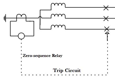
Such a relay will ignore load currents or phase-to-phase short circuits. Hence the setting of such relay will have no bearing on the load current values which is often essential for discrimination or even for adequate protection when earth currents are limited.
AC bridge :
A.C. bridges are electrical networks, based upon the extension of the Wheatstone bridge principle, used for the determination of an unknown impedance by comparison with known impedances and for the determination of frequency.
The various types of a.c. bridges are,
- Capacitance comparison bridge
- Inductance comparison bridge
- Maxwell’s bridge
- Hay’s bridge
- Anderson bridge
- Schering bridge
- Wien bridge
A simple Wheatstone AC bridge contains four impedance arms, A balanced detector which is sensitive to alternating currents and an A.C power supply. It is more difficult to achieve balance in an a. c. bridge than in a d.c. bridge because both the magnitude and the phase angle of impedances are related to the balance condition.
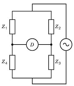
The condition for balance is the same as Wheatstone bridge but instead of resistances, impedances are used i.e.
Z1Z3 = Z2Z4
As stated earlier in an AC bridge, There should be the balance for the magnitudes of the impedances as well as the phase angle between them.Writing the impedances in their polar form, the above condition becomes
|Z1Z3|ej(Φ1 + Φ3) = |Z2Z4|ej(Φ2 + Φ4)
Hence, we see that, in fact, there are two balance conditions which must be satisfied simultaneously in a four-arm a.c. impedance bridge.
Z1Z3 = Z2Z4 &
Φ1 + Φ3 = Φ2 + Φ4
Thus, the balance of an ac bridge is obtained when the products of the magnitudes and the sum of the phase angles of the impedance in the pairwise opposite arms are made equal.