
Ques 4(a). Explain the braking methods of DC series motors
Sol:-The process of bringing the motor to rest within the predetermined time is known as braking.
A good braking system must have the following features:
- Braking should be fast and reliable.
- Force exerted by it should be controllable
- The equipment to stop the motor should be in such a way that the kinetic energy of the rotating parts of the motor should be dissipated as soon as I brakes are applied.
Braking applied to bring the motor to rest position is of two types and they are:
1. Electric braking.
2. Mechanical braking.
Mechanical braking
In this process of braking, the kinetic energy of the rotating parts is dissipated in the form of heat by the brake shoes of the brake lining that rubs on a wheel of vehicle or brake drum.
Electric braking
In this process of braking, the kinetic energy of Be rotating parts of the motor is converted into electrical energy which in turn is dissipated as heat energy in a resistance or in sometimes, electrical energy is returned to the supply. Here, no energy is dissipated in brake shoes.
TYPES OF ELECTRIC BRAKING
Electric braking can be applied to the traction vehicle, by any one of the following methods, namely:
1. Plugging
2. Rheostatic braking.
3. Regenerative braking.
Plugging
- Plugging It is also called reverse current braking.
- The connections of the motor are reversed, reversing the direction of torque, thereby bring it to a quick stop. For this, either the direction of field current or the direction of armature current is reversed.
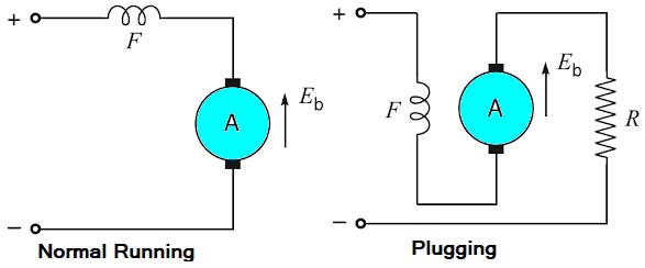
- The field circuit usually has a large time constant due to the high value of inductance, so the time taken to bring the field current to zero is large. Hence, it is usual to reverse the armature current.
- On reversing the armature current the supply voltage to the armature and back emf developed in it are additive. So, this condition is worse than the starting condition as the applied voltage to the armature is approximately double (V+E = 2V) to the supply voltage.
- Hence, an external resistance is inserted in the armature circuit simultaneously with the reversal of the armature current. Braking torque can be regulated by varying the magnitude of this resistance.
The disadvantages of this method are:
1. The kinetic energy of the motor is dissipated in the external resistance in the form of heat. So, this method of braking is inefficient.
2. The braking in this method fails in case of failure of the supply.
Rheostatic braking
- Rheostatic braking is also called as dynamic braking
- In rheostatic braking, the armature is cut off and the armature and the motor are connected in series with a variable resistance. The field is still energized.
- The motor, during braking, works as a generator feeding the resistance.
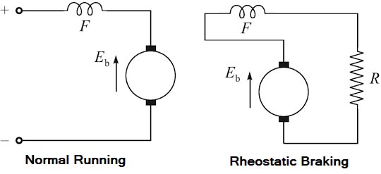
- The kinetic energy of the motor is converted to electrical energy during the period of braking till finally the motor stops.
- The electrical energy is dissipated in the resistance in the form of heat.
- Care must be taken that the direction of current through the field winding does not change.
- The external resistance should be of a value less than that of the critical resistance, which is a condition for a self-excited generator to build up.
- The magnitude of the braking torque can be regulated by varying the value of external resistance.
The disadvantage of the method is that the kinetic energy of the motor is dissipated as heat in the resistance and it is a wastage. The armature current and so the magnetic field changes with the change in speed. Therefore, the speed-torque curve is not linear in case of the series motor.
Regenerative braking
- In regenerative braking, the motor, instead of being disconnected from the supply, remains connected to the supply and returns the braking energy to the supply line. So, the wastage of kinetic energy in the plugging and rheostatic braking methods is prevented in the regenerative braking. This method the drives cannot be brought to the standstill. It reduces the speed to a minimum permissible value.
- In case of a d.c. series motor, increase in excitation results decrease in speed. As such it is not possible to get e.m.f. more than voltage. It is not possible to make field current more than the armature current. Hence regeneration braking with series motors is not possible. But can be used with traction motors with some special arrangements.
- In one method of regenerative braking with a single series motor, the motor is provided with a main series field winding and a few auxiliary field windings.
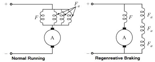
- For normal running, all the field windings are connected in parallel as shown in above Fig.
- During braking period the auxiliary windings are connected in series with each other and this series connected windings are connected in parallel with the series motor, and then, connected across the supply.
- The machine acts as a compound generator, slightly differential. Such an arrangement is quite stable. A change in the line voltage causes a corresponding change in excitation which produces a change in the induced emf. Thus, the change in line voltage is compensated.
Advantages of the electric braking over the mechanical braking
- The electric braking is smooth, fast, and reliable.
- Higher speeds can be maintained; this is because the electric braking is quite fast. This leads to the higher capacity of the system.
- The electric braking is more economical; this is due to excessive wear on brake blocks or brake lining that results in frequent and costly replacement in mechanical baking.
- Heat produced in the electric braking is less and not harmful but the heat produced in the mechanical braking will cause the failure of brakes.
- In the electric braking, sometimes, it is possible to feedback electric energy during the braking period to the supply system. This results in saving in the operating cost. This is not possible in case of mechanical braking.
Disadvantages of the electric braking
- During the braking period, the traction motor acts generator and electric brakes can almost stop the motor but it cannot hold stationary. Hence, it is necessary to employ mechanical braking in addition to electric braking.
- Traction motor has to work as a generator during the braking period. So that, the motor has to select in such a way that it should have suitable braking characteristics.
- The initial cost of the electric braking equipment is costlier.
Ques 4(b): Explain the parallel operation of 3-phase transformers
Sol:- Parallel operation of 3-phase transformers
The need for operation of two or more transformers in parallel often arises due to:
- Load growth, which exceeds the capacity of an existing transformer
- Lack of space (height) for one large transformer
- A measure of security (the probability of two transformers failing at the same time is very small)
- The adoption of a standard size of transformer throughout an installation
- To maximize the electrical power efficiency, availability, reliability, and flexibility.
When two or more transformers run in parallel, they must satisfy the following conditions.
- Same voltage ratio of transformers
- Same percentage impedance
- Same Polarity
- Same phase sequence
- Same voltage ratio
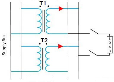
Same Voltage Ratio
An equal voltage ratio is necessary to avoid a no-load circulating current. Circulating current may be defined as that current which flows in transformers operating in parallel when they do not supply the load. Consider two transformers connected in parallel on their primary sides only. If the voltage readings on the secondaries are not same, there will be circulating currents between the secondaries when they are connected in parallel. This also creates circulating currents in primaries even when the load is not connected. As the internal impedance of the transformer is small, a small voltage difference may cause the high circulating current which increases copper losses. These circulating currents produce undesirable effects as under:
- They reduce the permissible output of the parallel combined group because circulating current produces unequal load sharing.
- They increase the power loss.
- They may overload one of the transformers.
Same percentage impedance
The current shared by two transformers running in parallel should be proportional to their MVA rating. And current carried by these transformers are inversely proportional to their internal impedance.Hence the impedance of the transformer running in parallel is inversely proportional to their MVA Rating Each transformer has a particular value of impedance which may be different from the other transformer i.e their resistance to reactance is different.
Consider two transformers whose ratings are in the ratio of 4: 1. It is obvious that the first transformer must have one-fourth of the impedance of the second transformer hence the current drawn by the first transformer will be 4 times to the second transformer
Due to the difference in the quality of percentage impedance, there will be the divergence of the phase angle of the two currents so that one transformer will be working with a lower and other with a higher power factor than the combined load.
Same Polarity.
The polarity of all transformer running in parallel must be same. The polarity of transformer refers to the instantaneous direction of Induced EMF in the secondary. If the instantaneous direction of induced secondary EMF in two transformers are opposite to each other when the same input power is fed to both of the transformers, then the transformer is said to be in opposite polarity. If the instantaneous direction of induced secondary EMF in two transformers are sane when the same input power is fed to both of the transformers, then the transformer is said to be in the same polarity.
The difference in the polarity causes huge circulating current that flows in the transformer and even may lead to the dead short circuit.
Conditions for parallel operation of Three phase transformer
The following conditions are to be fulfilled if two or more Three-phase transformers are to be operated successfully in parallel to deliver a common load.
Same Voltage Ratio
Both the transformers should have same transformation ratio i.e., the voltage ratings of both primaries and secondaries must be identical. If this condition is not exactly fulfilled i.e. if the two transformers have slight difference in their voltage or transformation ratios even then the parallel operation is possible. But for the satisfactory parallel operation, the circulating current should not exceed 10% of the normal load current.
Same percentage impedance
Both the transformers should have the same percentage (or per unit) impedance. If this condition is not exactly fulfilled, i.e., the impedance triangles at the rated kVA are not identical in shape and size, even then the parallel operation will be possible, but the power factors at which the transformers operate will differ from the power factor of the load. Therefore, in this case the transformers will not share the load in proportion to their kVA ratings.
Same phase Sequence
Both three-phase transformers must have the same phase-sequence i.e., the transformers must be properly connected with regard to their phase-sequence. If this condition is not observed, the secondary of one transformer will act as a load on the otherwise, the secondaries will be under short circuit condition, they will be heated up and damage the insulation quickly This condition must be fulfilled by all means.
Same Polarity
The difference in the polarity causes a huge circulating current that flows in the transformer and even may lead to the dead short circuit.
Important point regarding three-phase transformer
- In dealing with 3-phase transformers, calculations are made for one phase only. The value of equivalent impedance used is the equivalent impedance per phase referred to secondary.
- In case the impedance of primary and secondary windings are given separately, then primary impedance must be referred to secondary by multiplying it with (transformation ratio)
- For Y/D or D/Y transformers, it should be remembered that the voltage ratios as given in the questions, refer to terminal voltages and are quite different from turn ratio.
Ques 4(c):- Draw and explain equivalent circuit of a 1–phase transformer. Draw its phasor diagram
for leading power factor load.
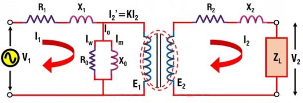
The term equivalent circuit of a machine means the combination of fixed and variable resistances and reactances, which exactly simulates performance and working of the machine.
For a transformer, no load primary current has two components,
Im = Io sinΦo = Magnetizing component
Ic = Io cosΦo = Active component
Im produces the flux and is assumed to flow through reactance Xo called no-load reactance while Ic is active component representing core losses hence is assumed to flow through the reactance Ro. Hence equivalent circuit with no load can be shown as in the Fig. This circuit consisting of Ro and Xo in parallel is called exciting circuit. From the equivalent circuit we can write,
[latex]\begin{array}{l}{R_o} = \dfrac{{{V_1}}}{{{I_c}}}\\\& \\{X_o} = \dfrac{{{V_1}}}{{{{\mathop{\rm I}\nolimits} _m}}}\end{array}[/latex]
When the load is connected to the transformer then secondary current I2 flows. This causes the voltage drop across R2 and R2. Due to I2, primary draws an additional current I2‘ = I2/ K where K is transformation ratio. Now I1 is the phasor addition of Io and I2‘. This I1 causes the voltage drop across primary resistance R1 and reactance X1. Hence the equivalent circuit can be shown as in the Fig.
But in the equivalent circuit, windings are not shown and it is further simplified by transferring all the values to the primary or secondary. This makes the transformer calculation much easy. So transferring secondary parameters to primary we get,
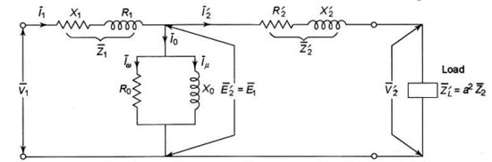
[latex]\begin{array}{l}R{‘_2} = \dfrac{{{R_2}}}{{{K^{_2}}}}\\\\{\rm{ }}X{‘_2} = \dfrac{{{X_2}}}{{{K^{_2}}}}\\\\Z{‘_2} = \dfrac{{{Z_2}}}{{{K^{_2}}}}\\\\While{\text{ E}}{‘_2} = \dfrac{{{E_2}}}{{K’}}{\text{ \& I}}{{\rm{‘}}_2} = K{I_2}\\\\Where{\text{ K = }}\dfrac{{{N_2}}}{{{N_1}}}\end{array}[/latex]
While transferring the value remember the rule that
- Low voltage winding → High current → Low Impedance
- High voltage winding → Low current → High Impedance
Now the primary value can be referred to the secondary side and we can obtain the equivalent circuit referred to the secondary.
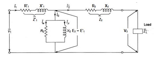
[latex]\begin{array}{l}R{‘_1} = {K^{_2}}{R_1}\\\\{\rm{ }}X{‘_1} = {K^{_2}}{X_1}\\\\Z{‘_1} = {K^{_2}}{Z_1}{\text{ \& E}}{‘_1} = K{E_1}{\rm{ }}\\\\{\rm{I}}{{\rm{‘}}_{\rm{1}}} = \dfrac{{{I_1}}}{K}{\text{ \& I}}{{\rm{‘}}_{\rm{o}}} = \dfrac{{{I_o}}}{K}\end{array}[/latex]
Now as long as no load branch is in between Z1 and Z’2, the impedance cannot be combined. So further simplification of the circuit can be done such circuit is called approximate equivalent circuit.
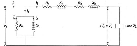
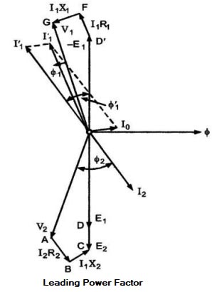
Diagram of leading Power factor
In leading power factor the current I2 leads the voltage V2 by an angle Φ
Ques 4 (d):- A 3–phase 400 V, 50 Hz 6-pole star connected induction motor develops maximum torque at a speed of 940 rpm. If the rotor resistance per phase is 0.1 Ω, determine the standstill rotor reactance.
Sol:- Given P = 6
Nr = 940 RPM
Frequency f = 50 Hz
Rotor resistance R = 0.1Ω
Synchronous speed Ns = 120f/P
= 120 x 50/6 = 1000 RPM
Slip of an induction motor is given as
[latex]\begin{array}{l}s = \dfrac{{{N_s} – {N_r}}}{{{N_s}}}\\\\ = \dfrac{{1000 – 940}}{{1000}} = \dfrac{{60}}{{1000}}\\\\s = 0.06\end{array}[/latex]
Condition for maximum torque
R = sX
- The induced torque is maximum when rotor resistance per phase is equal to the slip times the rotor reactance per phase under running condition. i.e R = S*X
- Note: Maximum torque is inversely proportional to the standstill reactance of the motor therefore to achieve maximum torque X, and therefore inductance of the rotor should be kept as small as possible.
X = R/s = 0.1/0.06
X = 1.667Ω/phase