
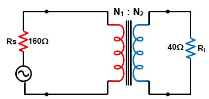
Ques 4(a):- A 160Ω source is to be matched to a 40Ω, 2 W load by means of a transformer. What is the turn ratio? Determine the primary and secondary voltage and current.
Sol:- Impedance matching is the practice of designing the input impedance of an electrical load or the output impedance of its signal source to maximize the power transfer or minimize signal reflection from the load.
The maximum power transfer theorem states that the resistance of the load must equal to the resistance of the source, to transfer the maximum amount of power from the source to load.
Now in the given question, the quantities given are:-
Source Resistance Rs = 160Ω
Load resistance RL = 40Ω
Load power PL = 2 W
(i):- Turn ratio
To transfer the maximum Power there should be no voltage drop and the losses are negligible. Hence the transformer works as an Ideal transformer such that
[latex display=”true”]\dfrac{{{V_1}}}{{{V_2}}} = \dfrac{{{N_1}}}{{{N_2}}} = \dfrac{{{I_2}}}{{{I_1}}}[/latex]
The primary input Resistance Rs is given by
[latex]\begin{array}{l}{R_s} = \dfrac{{{V_1}}}{{{R_1}}}\\\\ = \dfrac{{\left( {{N_1}/{N_2}} \right){V_2}}}{{\left( {{N_2}/{N_1}} \right){I_2}}} = {\left( {\dfrac{{{N_1}}}{{{N_2}}}} \right)^2}\dfrac{{{V_2}}}{{{I_2}}}\\\\{\text{Since the Load Resistance }}{{\rm{R}}_{\rm{L}}}{\rm{ = }}\dfrac{{{V_2}}}{{{I_2}}}\\\\\therefore {R_s} = {\left( {\dfrac{{{N_1}}}{{{N_2}}}} \right)^2}{{\rm{R}}_{\rm{L}}}\\\\or{\text{ }}\dfrac{{{R_s}}}{{{{\rm{R}}_{\rm{L}}}}} = {\left( {\dfrac{{{N_1}}}{{{N_2}}}} \right)^2}\\\\\dfrac{{160}}{{40}} = {\left( {\dfrac{{{N_1}}}{{{N_2}}}} \right)^2}\\\\\sqrt {\dfrac{{16}}{4}} = \left( {\dfrac{{{N_1}}}{{{N_2}}}} \right)\\\\\dfrac{{{N_1}}}{{{N_2}}} = \dfrac{2}{1}\end{array}[/latex]
(ii):- Primary and secondary voltage
Secondary Voltage
Since the load power Is given i.e 2 Watts
[latex]\begin{array}{l}P = \dfrac{{{V_2}^2}}{{{R_L}}}\\\\2 = \dfrac{{{V_2}^2}}{{40}}\\\\{V_2} = 8.94V\end{array}[/latex]
Primary Voltage
As we Know that
[latex]\begin{array}{l}\dfrac{{{V_1}}}{{{V_2}}} = \frac{{{N_1}}}{{{N_2}}}\\\\\dfrac{{{V_1}}}{{8.94}} = \dfrac{2}{1}\\\\{V_1} = 17.88V\end{array}[/latex]
(iii). Primary and secondary current
Primary current
I1 = V1/RS = 17.88/160 = 0.11 A
Secondary current
I2 = V2/R2 or P/V2
= 8.94/40 = 0.22 A
Ques 4 (b). Explain the various losses in a transformer. Derive the condition for maximum efficiency of the transformer.
Ans 4(b):- In a transformer electrical energy is transferred from one circuit to the other. The whole of the input energy cannot be transferred to the output circuit as a certain amount of it is lost in the core and the windings of the transformer as heat. By proper design of a transformer, the losses are kept as minimum as possible.
It may be mentioned that total losses in a transformer are less than that in an equivalent electrical rotating machine as there is no rotational loss in a transformer.
Losses In Transformer
Basically, there is 2 Type of Losses In a transformer
- Copper Losses(or I2R losses and Ohmic Losses) In the primary and secondary Winding. The copper Losses (Pc) has two components
- Primary Winding copper losses
- Secondary winding copper losses
- Iron losses (or core Losses) In the core. The Iron Losses is further divided into two Hysteresis
- Hysteresis Losses
- Eddy current Losses
Copper losses:– When the transformer is loaded, current flows in the primary and secondary winding, there is a loss of electrical energy due to the resistance of the primary winding and secondary winding.These losses depend upon the loading conditions of the transformers. The copper losses depend on the magnitude of the current flowing through the windings. Although the resistance of the winding is kept as low as possible and copper losses can only be prevented if the current is reduced to zero.
The copper losses are denoted as Pcu. If the current through the windings is full load current, we get copper losses at full load. If the load on the transformer is half then we get copper losses at half load which is less than full load copper losses. Thus copper losses are called variable losses.
Power loss in the resistive circuit is given by the expression P = I2R and since winding resistance is almost constant the copper losses depend upon the square of the load current.
[latex display=”true”]{\text{Copper Loss = }}{\left( {\dfrac{{{\text{Actual Load}}}}{{{\text{Full Load}}}}} \right)^2} \times {\text{Full load copper loss}}[/latex]
Core loss occurs due to the core of the transformer. As the core of transformer is made up of ferromagnetic material so these losses occur
Hysteresis loss: A transformer core is made up of ferromagnetic material and these materials are very sensitive to magnetization.These materials behave as magnates when the external magnetic field is applied.These materials having the number of domains in their structure and the domains are nothing but small permanent magnets whose axes are randomly oriented inside the material so net magnetization is zero.
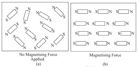
But when an external magnetic field is applied, the axes of domains(small magnets) get aligned to the axis of externally applied magnetic field and when this external magnetic field is removed, maximum domains attain their original position but some of them do not attain their position means material do not demagnetise completely and this is the reason for hysteresis loss. In the transformer, we give AC supply so after each half cycle reversal of external magnetic field, so there is a reversal of domain, Hence extra work has to be done to completely reverse it and this extra work needs electrical energy which results in hysteresis loss.
Hysteresis Losses is given by
Hysteresis Loss = Kh × BM1.67 × f × v watts
where
Kh = Hysteresis constant depends upon the material
Bm = Maximum flux density
f = frequency
v = Volume of the core
Eddy current loss: In transformer we provide alternating current in primary which produces alternating flux in core ,this flux links with secondary of transformer and induces emf in secondary, it may be possible that flux also links with some other conducting parts of transformer such as ferromagnetic core or iron body and induces local emf in these parts of transformer which will cause a circulating current to flow in these parts causing heat loss.these currents are called eddy current and this loss is called eddy current loss.
Eddy current losses in the transformer is given by
Eddy current losses = Ke × Bm2 × f2 × t2
Where Ke = Eddy current constant
t = thickness of the core
Efficiency of the transformer
Due to the losses in a transformer, the output power of a transformer is less than the input power supplied.
∴ Power Output = Power Input − Total Losses
Power Input = Power Output + Total Losses
= Power Output + Pcu + Pi
The efficiency of any device is defined as the ratio of the power output to the power Input. Therefore Efficiency
[latex]\begin{array}{l}\eta = \dfrac{{{\text{Power Output}}}}{{{\text{Power Input}}}}\\\\\eta = \dfrac{{{\text{Power Output}}}}{{Power{\text{ }}Output{\rm{ }} + {\rm{ }}{P_{cu}} + {\rm{ }}{P_i}}}\end{array}[/latex]
Now Power Output = V2 I2 Cosφ
Where Cosφ is the load power factor
Let the transformer supply full load current I2 and with terminal voltage V2.
Pcu = Copper losses on full load = I22R2e
[latex]\begin{array}{l}\eta = \dfrac{{{V_2}{I_2}Cos{\Phi _2}}}{{{V_2}{I_2}Cos{\Phi _2} + {P_i} + {I_2}^2{R_{2e}}}}\\\\{\text{Dividing both Numerator and Denominator By }}{{\rm{I}}_{\rm{2}}}\\\\\eta = \dfrac{{{V_2}Cos{\Phi _2}}}{{{V_2}Cos{\Phi _2} + \dfrac{{{P_i}}}{{{I_2}}} + {I_2}{R_{2e}}}}\end{array}[/latex]
Condition for Maximum Efficiency Of transformer
When a transformer works on a constant input voltage and frequency then efficiency varies with the load. As load increases, the efficiency increases. At a certain load current, it achieves a maximum value. If the transformer is loaded further the efficiency starts decreasing.
The Load current at which efficiency attain the maximum value is denoted as I2m and the maximum efficiency is denoted as ηmax.
The efficiency is the function of load i.e Load current I2 assuming cosφ2 constant. The secondary terminal voltage V2 is also assumed to be constant.
To determine the maximum efficiency differentiate the denominator with respect to I2 and equate to zero, thus
[latex]\begin{array}{l}\dfrac{d}{{d{I_2}}}\left( {\dfrac{{{V_2}Cos{\Phi _2}}}{{{V_2}Cos{\Phi _2} + \dfrac{{{P_i}}}{{{I_2}}} + {I_2}{R_{2e}}}}} \right)\\\\{\text{or }}\dfrac{{{P_i}}}{{{I_2}}} + {R_{2e}} = 0\\\\{I_2}^2{R_{2e}} = {P_i}\end{array}[/latex]
Hence the efficiency will be maximum at a load in which the total copper-loss in the windings is equal to the core-loss. A transformer is designed such that its efficiency is generally maximum at a load slightly lower than the full-load. This is because the transformer generally works at a load lower than the full-load rating (when a transformer is installed, its rating is chosen higher than the estimated load). Thus by design, the transformer is put to work at near maximum efficiency.
Ques 4(c). A direct current shunt motor develops 10 HP at 8000 RPM when drawing a line current of 40 A at 220 V. Find the efficiency at this load and the useful torque.
Power Input
For a resistor in a DC Circuit, the power is given by the product of applied voltage and the electric current. i.e
P = V.I watt
Pi = 220 × 40 = 8800 W
Power Output
1 HP=745.7 Watt of Power
10 HP = 7457 Watt of Power
[latex]\begin{array}{l}Efficiency = \dfrac{{Output}}{{Input}}\\\\ = \dfrac{{7457}}{{8800}} = 85.3\% \end{array}[/latex]
Power output of DC Motor is given as
Pout = 2πNT/60
Where T = torque in Newton /meters (Nm)
Pout = power output in watts (W)
n = the speed of rotation in revolution per minute (rpm).
or
[latex]\begin{array}{l}T = \dfrac{{60{P_{out}}}}{{2\pi N}}\\\\T = \dfrac{{7457 \times 60}}{{2\pi \times 8000}}\\\\{\text{T = 8}}{\text{.90 Nm}}\end{array}[/latex]
Ques 4(d). Explain the effect of frequency variation on torque-speed characterstics of a 3 phase induction motor.
The torque of rotor under running condition is
Slip Corresponding to Max torque
S = R2/X2
Putting the value of slip in above equation we get
[latex]\begin{array}{l}T = \dfrac{{K{R_2}/{X_2}{E_2}^2}}{{{R_2}^2 + \left( {{R_2}^2 + {X_2}^2} \right){X_2}^2}}\\\\T = K\dfrac{{{E_2}^2}}{{2{X_2}}}\end{array}[/latex]
E2 = Rotor induced E.M.F per phase on standstill condition Which is directly proportional to applied voltage
Hence Torque T ∝ sV2
From the above equation, it is clear that the torque at any speed is directly proportional to the square of the voltage. If the voltage is decreased by 10%, then the torque is decreased by 20%. Changes in supply voltage not only affect the starting torque Tst but torque under running conditions also. If V decreases, then T also decreases.
Hence, for maintaining the same torque, slip increases i.e. speed falls
Let V Changes To V”, s to s” and T to T”
Then T/T” = sV2/s”V”2
Variable Frequency Control
- The full load operating speed of the 3-phase induction motor is very close to the synchronous speed. As such, for the variation in operating speed, the synchronous speed of the motor can be changed.
- The synchronous speed of 3-phase induction motor for a fixed number of stator poles depends directly on the frequency of the voltage applied to the stator winding, that is N. = 120f/ P. Thus, the speed control of the motor over a wide range with smooth control is obtained by varying the frequency of the voltage applied to the stator winding of the motor. However, with variation in the frequency, the air gap, φ changes, as shown by the induced emf equation given below.
The emf induced in the stator winding per phase E1 = 4.44 fφT1Kw1
- However, the induction motor should be operated at rated air gap flux, to avoid saturation and to minimize the losses. Thus, it is essential to keep, E1/f or V1/f constant, in order to operate the motor at different speeds by varying the frequency, to keep the air gap flux constant.
- The figure shows the torque-speed characteristics of 3-phase induction motor with variable frequency, variable voltage (V/f = constant) applied to the stator winding. The characteristic of load torque is also shown in the same diagram figure
- At all the variable frequencies, the air gap flux is maintained constant by keeping V/f constant. Since an increase in the supply frequency increases the power factor but decreases the torque. On to other hands, a decrease in the supply frequency decreases the power factor but increases the torque.
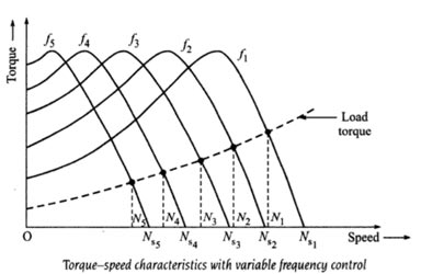
- Therefore keeping the V/f ratio constant, the same maximum torque is obtained with all frequencies. The following conclusions can be easily drawn from the Torque-speed characteristics.
- The terminal voltage across the stator winding is changed, as the frequency is varied, ascertaining that Vlf is constant at all operating frequencies. Hence, a variable voltage, variable frequency source is essential to feed the stator winding of the motor.
- The wide speed variation, from N1 to N5 that is from rated speed to lower region of speed can be obtained by applying variable frequency, the variable voltage to the motor, with Vlf constant.
- The operating slip in all the above cases (speed variation from N1 to N5) is low and hence, the operating efficiency is high.
- The performance of the motor is much better, as compared to other methods of speed control.
- By changing the supply frequency, the speed of the motor can be increased or decreased smoothly. However, the supply frequency available from the electricity supply authority is at 50 Hz which is fixed.
- Frequency conversion equipment is, therefore, needed for speed control of motors. Variable frequency supply can be obtained from a separate motor generator set, rotary converters, or solid state electronic devices.
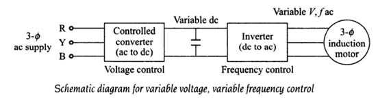
- The controlled converter, rectifies the 3-phase, ac supply of standard frequency and voltage to a dc of variable voltage.
- The voltage can be varied, as per the requirement of the frequency variation. The dc variable voltage is inverted to 3-phase AC with variable frequency and variable voltage by a 3-phase inverter.
- The frequency control is obtained by the inverted. Thus, with the above circuit, it is possible to obtain a variable frequency, the variable voltage source with V/f constant, to be applied to the 3-phase induction motor.
- The frequency changing device should change frequency and applied Voltage, simultaneously as a direct ratio. the f frequency is increased, the supply voltage must also be increased and if the frequency is decreased, supply voltage must also be decreased proportionally. This will keep the torque developed constant and the operating efficiency high.