
Ques 5(a). Explain the cause and effect of Low Power factor in a power system.
Ans.
Cause of Low Power Factor
- Power factor is defined as the ratio of KW to KVA, we see that low power factor results when KW is small in relation to KVA. Inductive loads (which are sources of Reactive Power) include:
- Transformers
- Induction motors
- Induction generators (windmill generators)
- High-intensity discharge (HID) lighting.
Low PF (less than 0.8) is undesirable from the economic point of view. These inductive loads constitute a major portion of the power consumed in industrial complexes.
- Extensive use of induction motor. At full load, the PF of an induction motor may around of 85% and at reduced loads, the power factor is much lower.
Full load, Pf = 0.8 -0.9
Small load, Pf = 0.2 -0.3
No Load, Pf may come to Zero (0).
- Varying Load in Power System(As we know that load on the power system is varying. During low load period, the supply voltage is increased which increase the magnetizing current which causes the decreased power factor).
- 90% of the industrial load consists of Induction Machines (1-ϕ and 3-ϕ). Such machines draw magnetizing current to produce the magnetic field and hence work at low power factor.
- Arc lamps also operate at low power factor due to the varying nature and characteristic of the arc.
- A transformer draws magnetizing current which causes the total current to lag with repeat to the emf. At normal loads, the magnetizing current does not affect the power factor much but at light loads (say, a distribution transformer supplying mostly domestic lighting load only at night time), the primary current power factor is low.
- The power factor of the load is also reduced due to increased use of power electronic circuits.
- Reactive power (KVAR) required by inductive loads increases the amount of apparent power (KVA) in the distribution system.This increase in reactive and apparent power results in a larger angle (measured between KW and KVA).
- The industrial heating furnaces have very low larding PF.
Avoidance of low power factor
- It is preferable to use synchronous motors in comparison with induction motors wherever possible.
- Preference should be given to the use of high-speed induction motors in comparison with low-speed motors.
- If possible, induction motors should be operated at its rated output. In this regard, a group drive is the better choice than that of the individual drive.
- In case, a 3-phase induction motor has to operate for considerable periods at less than half load, stator winding which is normally in Delta may be switched into the star. The arrangement improves the PF of the motor considerably. In addition, efficiency at fractional loads is improved.
- In some typical situations, do motors fed from the synchronous motor driven generator may be used in preference to induction motor driven generator. Such an arrangement has added the advantage of providing variable speed with dc motors.
Effects or disadvantages of low power factor
- Higher Load current: The load current IL = P/√3VLcosφwhere P is the real power (watts).From the above expression for a given load, it is clear that if the pf is low, the load current will be higher. The larger the load current due to low pf results in the following effects.
- Effect on transmission lines: For the fixed active power to be transmitted over the line, the lower the pf, the higher will be the load current to be carried by the line. Since the maximum permissible current density of the line conductor is fixed, the cross-sectional area of the conductor is to be increased in order to carry larger current. This results in an increased volume of the conductor material which in turn increases the capital cost of transmission lines.Further, increase in the current causes increase in the line losses with a reduction in the efficiency of the line. Also, the line voltage regulation is poor.
- Effect on transformers: A reduction in the pf causes a reduction in the kW capacity of a transformer.
- Effect on switchgear and bus bar: The lower the pf at which a given power is to be supplied, the larger is the cross-sectional area of the bus bar and the larger is the contact surface of the switchgear.
- Effect on generators: With a lower pf, the kW capacity of a generator is reduced. The power supplied by the exciter is increased. The generator copper losses are increased, which results in low efficiency of the generator.
- Effect on prime movers: When the pf is decreased, the alternator develops more reactive kVA, i.e., the reactive power generated is more. This requires a certain amount of power to be supplied by the prime mover. So, a part of the prime mover capacity is idle and it represents a dead investment. The efficiency of the prime mover is reduced.
Note:- Method of power factor correction is well explained in SSC conventional Paper 2017
Ques 5 (b). Explain why a three-phase induction motor is self-starting and a single-phase induction motor is not.
Ans:
Why is 3 – phase Induction Motor is self-starting?
- 3 phase induction motor is self-starting because it consists of cage windings of parallel conductors (made up of copper or aluminum) short-circuited at the ends by end rings, hence forming a closed path for current flow.
- And for SLIP RING induction motor the ends of the rotor windings are externally connected by a variable rheostat (resistance is varied in order to give it proper starting and running current).
- The three-phase induction motor is self-starting due to rotating magnetic field. This magnetic field cuts the rotor conductors and exerts the force on them which cause the rotor to turn.
Let us Explain in detail
Prerequisites to understand the working of 3 phase induction motor
- When a three-phase voltage is given to the three-phase winding a rotating magnetic field is set up.
- Lenz’s law: Whenever there is a change in magnetic field associated with a conductor loop, the emf induced in the conductor always tend to decrease the cause of the effect i.e., decrease the ‘change in magnetic field’ not the magnitude of magnetic field.
WORKING :
- Both the stator and rotor windings are wound in a 3 phase winding.
- Whenever a supply is given to 3 phase stator windings a rotating magnetic field is set up.
- The rotor of the induction motor consists of a number of individual conductors, or bars, embedded in slots which run the length of the rotor. The rotating magnetic field induces voltages and currents in these rotor bars.
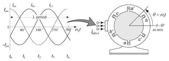
- This rotating magnetic field links with stationary 3 phase winding of rotor, as a result, induces a 3 phase emf in 3 phase winding.
- As per Lenz’s law, the rotor tries to rotate with the speed of rotating magnetic field so that there won’t be any change in the magnetic field linked to it.
- With properly located and designed windings, the magnetic field created by all three-phases combines to produce a single rotating flux wave of constant magnitude and speed of rotation.
- Once it reaches the speed of rotating magnetic field the motor stops rotating as there is no change in the magnetic field linked to the rotor.
- So the speed reduces and again emf is induced due to change in speed of the rotor and rotating magnetic field.
- The interaction of the magnetic field with the rotor currents creates a force on the rotor that comes close to accelerating to the speed of the rotating magnetic field.
- The rotor can never reach the speed of the rotating field because of the relative motion between the rotor and field which creates the induced currents, and hence, the torque.
- Even if there is no load connected to the motor, there will be friction and windage losses, so the motor accelerates to a speed just below the speed of rotation of the magnetic field.
- The speed of rotation of the magnetic field depends on the number of poles and the frequency of the applied three-phase voltage.
Why is single phase Induction Motor not self-starting?
The working principle of an ac machine is primarily “one field following another field”. In the case of a multiphase induction motor, there will be a virtual rotating magnetic field. But considering the case of a single phase induction motor, it’s only a pulsating field that is produced and not a rotating one. This can also be explained on the basis of ‘DOUBLE REVOLVING FIELD THEORY‘, which is based on Ferraris Principle
According to Ferraris principle, “the magnetic field produced by single-phase alternating current, can be replaced exactly by two rotating fields of half its amplitude traveling in opposite directions at synchronous speed”.
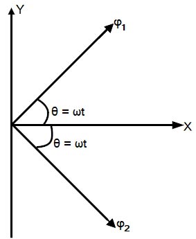
Lets us consider that the alternating flux, produced by the 1-φ alternating current, at any instant is given by
φ = φm cosωt
Where φm is the maximum value of flux
Now, this alternating flux can be resolved into two components. The first component of flux traveling
in the clockwise direction.
φcw = φm/2
Second component of flux traveling in counter-clockwise direction
φacw = φm/2
Now assumed that the rotor is given a push in any one direction say in the clockwise direction, and is running with a speed of Nr rpm.
The flux component revolving in the clockwise direction φcw will have a synchronous speed
Ns = 120f/P
And the flux revolving in counter-clockwise direction φacw will have the synchronous speed
Ns = −120f/P————–(1)
The per unit slip of the first component φcw will be
[latex display=”true”]{s_{cw}} = \dfrac{{{N_s} – {N_r}}}{{{N_s}}} = s—–2[/latex]
Similarly, the per unit slip of the second component φacw will be
[latex display=”true”]\begin{array}{l}{s_{cw}} = \dfrac{{ – {N_s} – {N_r}}}{{ – {N_s}}}\\\\ = \dfrac{{{N_s} + {N_r}}}{{{N_s}}}——(3)\end{array}[/latex]
From equation 1, 2 and 3
sacw = 2 – scw
At the time of starting
scw = 1
∴ sacw = 2 – 1 = 1
The torque of an Induction motor is directly proportional to the slip
I.e T ∝ s
Therefore the resultant Torque
Tr = Tcw − Tacw
= 1 − 1 = 0
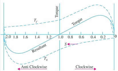
Therefore Average torque at standstill is zero and, therefore, the motor is not inherently self-starting(at zero speed, the torque developed by the fort yard and backward fields cancel each other).
Ques 5 (c). Explain why a synchronous Motor develops torque at synchronous speed, whereas an induction motor develops torque at all speeds except the synchronous Speed.
Why Synchronous Motor Develops Torque at synchronous Speed?
The synchronous motor is a truly constant speed motor. This is the specialty of this motor. Yet, it has very limited applications. To develop a steady torque, its rotor must be rotating at synchronous speed, Ns. This is the major defect of synchronous motors. Either it runs at synchronous speed, or it does not run at all.
The stator field rotates at synchronous speed due to the three-phase currents supplied to its windings. In order to develop a continuous unidirectional torque, it is necessary that the stator and rotor poles do not move with respect to each other. This is possible only if the rotor also rotates at the synchronous speed. Therefore Magnetic Locking between the poles is necessary to do so.
Concept of Magnetic Locking
- Synchronous motor work on the principle of magnetic locking.
- When two unlike strong unlike magnets poles are brought together, there exists a tremendous force of extraction between those two poles. In such condition, the two magnets are said to be magnetically locked.
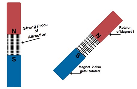
- If now one of the two magnets is rotated, the other magnets also rotate in the same direction with the same speed due to the strong force of attraction.
- This phenomenon is called as magnetic locking
For magnetic locking condition, there must be two unlike poles and magnetic axes of this two poles must be brought very nearer to each other.
- Consider a synchronous motor whose stator is wound for 2 poles.
- The stator winding is excited with 3 phase A.C supply and rotor winding with D.C supply respectively. Thus two magnetic fields are produced in the synchronous motor.
- When the 3 phase winding is supplied by 3 phase A.C supply than the rotating magnetic field or flux is produced.
- This magnetic field or flux rotates in a space at a speed called synchronous speed.
- The rotating magnetic field or rotating flux has fixed relationship between, the number of poles, the frequency of a.c supply and the speed of rotation.
- The rotating magnetic field creates an effect which is similar to the physical rotation of magnets in space with a synchronous speed.
- So for rotating magnetic field
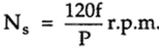 Where f = supply frequency
P = Number of poles
- Suppose the stator poles are N1 and S1 which are rotating at a speed of Ns and the direction of rotation be clockwise.
- When the field winding on a rotor is excited by the D.C source, it produces the two stationary poles i.e N2 and S2.
- To establish the magnetic locking between the stator and rotor poles the, unlike poles N1 and S2 or N2 and S1 should be brought near to each other.
- As stator poles are rotating and due to magnetic locking the rotor poles will rotate in the same direction of rotating magnetic field as that of stator poles with the same speed Ns.
- Hence synchronous motor rotates at only one speed that is synchronous speed.
- The synchronous speed depends on the frequency therefore for constant supply frequency synchronous motor speed will be constant irrespective of the load changed.
At zero speed or at any other speed lower than synchronous speed, the rotor poles rotate slower than the stator field. Therefore, in one cycle of rotation of the stator field, the N-pole of the rotor is for some time nearer to N pole of the stator and for some other time nearer to the S-pole of the stator. As a result, the torque developed is for some time clockwise and for some other time anticlockwise. Consequently, the average torque developed remains zero. Hence the Synchronous Motor Run either on Synchronous Speed Or Not at all.
Why an induction motor cannot run at synchronous speed?
- An induction motor works on the principle of electromagnetic induction.
- Now in an induction motor, we have a rotating magnetic field formed due to three phase supply.
- When the motor is stationary then due to this rotating magnetic field an EMF is induced in the rotor (Generating Action).
- Now rotor being shorted current starts flowing in it and due to motoring action torque is produced and the rotor starts rotating.
- When the rotor tries to rotate with the synchronous speed but when it reaches that speed the relative motion between magnetic field and conductor will become zero.
- Emf generated is given by
E=B*L*V,
where V is relative velocity=Vs-Vr,
L- the length of conductors,
B -magnetic field density. - So now consider, the rotor of Induction Motor achieved synchronous speed then relative velocity would be zero as rotor speed equals to rotating magnetic field’s speed (Vs = Vr), thus emf generated will be zero.
- No current flows through conductors so no force I.e. no torque. So because of the moment of inertia rotor will run even if emf is zero. And after some time, rotor speed decreases. again there would be relative velocity and again force-torque will generate making Induction Motor to rotate at speed less than synchronous speed
Ques 5 (d). Which fault in the power system is more severe as compared to other faults and why?
Ans5(d).
A fault in the line is any failure which interferes with the normal flow of current in the line. The fault may occur on a power system due to a number of reasons such as
- Lightning
- High-speed winds
- Snow
- Insulation failure
- Falling of tree on a line
During the occurrence of the current which flows in different parts of the power system immediately after the occurrence of the fault is much greater than that flowing a few cycles later. The exponential decay of fault current from an initial ‘transient’ value to a final ‘steady state’ value is due to the changing impedance offered to the fault by the system.
Types of Fault in Power System
Generally, the power system is categorized Into two main part i.e
- Symmetrical Fault
- Three phase Fault
- Asymmetrical Fault
- Double Line to ground fault L-L-G fault(Neutral Grounded)
- Line to Line fault (L-L fault)
- Line to Ground fault (L-G fault)
Symmetrical-Fault
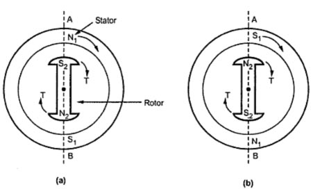
The fault in the power system which gives rise to the symmetrical current (i.e equal fault current in the lines with 120° displacement) is called as the symmetrical fault.
The most severe fault from the viewpoint of transient stability is a solid three-phase fault. This fault is the most severe since it reduces the voltage on all phases at the point of the fault to zero and eliminates any transfer of power past this point. The three-phase fault is Most severe but it less likely to occur (only 2- 3%). The most common fault is Line to Ground Fault.(85%)
The symmetrical fault occurs when all the three conductors of a 3-phase line are brought together simultaneously into a short-circuit condition as shown in Fig. This type of fault gives rise to symmetrical currents ie. equal fault currents with 120° displacement. Thus fault currents IR, IY and IB will be equal in magnitude with 120 displacements among them. Hence the same magnitude of current flows in all three phases and the grounding has no effect on these currents. Therefore when such a fault occurs, largest fault currents flow in the lines. For this reason, ratings of circuit breakers are decided on file basis of symmetrical shortcircuit calculations.
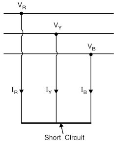
Because of balanced nature of the fault, only one phase need be considered in calculations since conditions in the other two phases will also be similar. A plot showing the critical clearing time for these four types of faults for a typical machine is shown in Figure.
The transient stability power limits versus switching time for a two-machine system is shown. As the switching time gets smaller, the difference between the severity of the faults also gets smaller and in the limit, the condition that produces instability is the switching out of the line. Based on this reasoning, we can say that the switching time of the three-phase fault is large hence it is most severe.
The faults in a power system have the following harmful effects on the system:
- Faults generally give rise to large currents which may damage the equipment in the line of the system.
- Large fault current overheats the system equipment. (iii) Some faults block the flow of power.
- Faults can cause the system to become unstable.
- Faults can cause the 3-phase system to become unbalanced and this affects the operation of 3-phase equipment.
Ques 5(e). What are the necessary conditions for the parallel operation of alternators?
The demand for power is increasing day by day. It is a challenge for power engineers to meet the power demand of customers. A single alternator cannot meet the power demand. To meet the excess power demand, additional alternators are connected in parallel. If a single alternator can meet the power demand, an outage of the alternator will cause interruption of power supply. On the other hand, paralleling of alternators ensures the supply of a part of the total demand when one alternator is out of order.
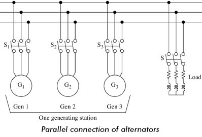
Reasons for Paralleling of Alternators
- The reasons for paralleling are
- A single alternator may not meet the local or regional power requirements.
- It is possible to shut down one or more alternators for scheduled or emergency maintenance when the alternators are operating in parallel. The load can be supplied.
- At part load, one or more alternators are shut down and the remaining load is carried out with few machines efficiently because alternators are inefficient at part load.
- It is possible to handle load growth by adding alternators without disturbing the original installation.
- The available machine prime movers and alternators can be matched to obtain economical cost and reliable use.
Condition for parallel Operation of an alternator
The following condition must be satisfied for parallel operation of an alternator
- Same Voltage Ratio
- Same Phase Sequence
- Same Frequency
Same Voltage Ratio:-
The voltages must be the same as the paralleling point or junction even though not the same at the alternators. During paralleling of two alternators, the voltages at the paralleling point must be the same. Any mismatch of the paralleling point voltage will cause the circulating current to flow between them. This will cause sufficient voltage drops through the armature resistance. This circulating current causes the I2R loss through the armature winding resistance, which results in heating of the generators and hence additional load on the prime movers. Therefore, this mismatch should be avoided.
Identical Phase Sequence
- The phase of the incoming machine must be identical to that of the bus. If the bus has phase sequence A-B-C, the incoming machine must have phase sequence. If the incoming machine has the phase sequence A-C-B, it will cause a disastrous short circuit.
- If the phase sequence A of the incoming machine and the bus is fully synchronized and phase sequences B and C of the incoming machine mate with the phase sequences C and B of the bus respectively, this mismatch between two phase sequences out of three phase sequences will result in short-circuit current, which is ultimately limited by the combined synchronous impedances of the windings involved.
- This short-circuit current will be even more at the moment of switch closure. This is because the armature reaction cross-magnetization needs time to be established. This out of phase sequence should be avoided very carefully.
Same Frequency Requirement
The frequency of the incoming machine must be identical to the frequency of the bus. If the frequency difference is very small and the alternator is in phase with the bus, the paralleling condition will be successful.
Relation of Prime Mover Torque Speed
The prime movers of the alternators must have drooping and similar speed-torque characteristic for perfect load sharing. Rising speed-torque characteristic must be avoided.
Advantage of Parallel Operation of Synchronous Generators
The following are the advantages of connecting a large number of synchronous generators in parallel to supply a common load:
- Continuity of Supply and Maintenance: Repair and maintenance of individual generating units can be done keeping the continuity of supply by properly scheduling maintenance of generators one after the other. If only one large generator is installed, supply is to be cut off for maintenance work.
- Efficiency: For operating an alternator on maximum efficiency it is to be run near to its full-load capacity. It is uneconomic to operate large alternators on low loads. If several small units are used. units can be added or put off depending upon the load requirement and thus the units can be operated at near to their rated capacity.
- Capital Cost: Additional sets can be connected in parallel to meet the increasing demand, thereby reducing the initial capital cost of buying larger units in anticipation of increasing demands.
- Size of Alternators: There is the physical and economic limit to the possible capacity of alternators that can be built. The demand for a single power station may be as high as 1200 MVA. It may not be feasible to build a single alternator of such a high rating due to physical and economic considerations.