
Ques 6 (a). What are the advantages and disadvantages of BJT and JFET?
Bipolar Junction Transistor (BJT)
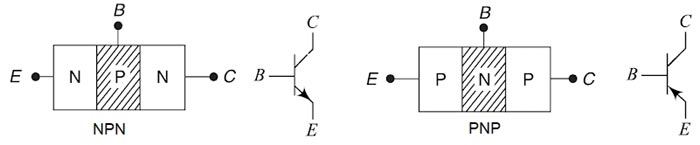
A Bipolar Junction Transistor (BJT) is a three-layer, two junction semiconductor device consisting of either two N-type and one P-type layer of material (NPN transistor) or two P-type and one N-type layer of material (PNP transistor). If a thin layer of N-type Silicon is sandwiched between two layers of P-type silicon. This transistor is referred to as PNP. Alternatively, in an NPN transistor, a layer of P-type material is sandwiched between two layers of N-type material.
The term bipolar is to justify the fact that holes and electrons participate in the injection process into the oppositely polarised material. If only one carrier is employed (electron or hole). it is considered a unipolar device.
Advantages of bipolar junction transistor (BJT) are as given below,
- The bipolar junction transistor (BJT) has a large gain bandwidth.
- The BJT shows better performance at high frequency.
- The large value of current gain, β
- The large value of transfer conductance gm
- The BJT has a better voltage gain.
- The BJT can be operated in low or high power applications.
- The BJT has high current density.
- There is the low forward voltage drop.
- BJTs have a very predictable turn on voltage, i.e. typically 0.7V Vbe
- A BJT needs a small amount of current to switch on the transistor.
- BJT amplifier stages are much more linear than MOSFET amplifier stages, as the gain doesn’t depend on the bias voltage. This gives better fidelity.
- BJT’s are capable of handling higher output currents for signal outputs and can have the lower output impedance. In amplifiers intended to drive a low input impedance load or deliver significant amounts of power, this is a huge advantage. Many of the highest quality op-amps are made with a BiCMOS process using a BJT pair for the output buffer stage.
Disadvantages of BJT
There are some disadvantages of bipolar junction transistor (BJT) are as given below,
- The bipolar junction transistor (BJT) more noise produced.
- Special isolation regions required between individual devices in an
- More number of diffusion steps required for its manufacturing
- Larger turn-off time
- Operation of the BJT relies on the transport of minority carriers and that is significantly affected by incident electromagnetic radiation. (Hence, the existence of photo-diodes and photo-transistors, etc.)
- BJT has a low thermal stability.
- BJT’s are current-operated devices rather than voltage-operated. Most of the time this means higher power consumption.
- BJT has a positive temperature coefficient at high current level. It means in BJT collector current increases with the increase in temperature. This characteristic leads the BJT to thermal breakdown.
- The switching frequency of BJT is low.
- It has a very complex base control. So it may lead to confusion and requires a skillful handling.
Junction Field Effect Transistor JFET
Historically, Field Effect Transistors (FETs) were developed in the early 1930s, much before BipolarJunction Transistors BJT). However, the FETs were not available commercially until 1950s,
The phenomenon of modulating conductance of a semiconductor material by an electric field applied perpendicular to the surface of a semiconductor is Known as field effect.Transistors, whose operation depends upon this field effect, are known as field effect transistors (FETs).
JFET is a three-terminal device with the source, drain, and gate as terminals. Its basic structure consists of a long semiconductor bar which forms the channel. The doping of the channel determines the type of Field Effect Transistor. A P-type doping results in P-channel JFET and n-type doping results in n-channel JFET. The figure shows the structure of the n-channel JFET.
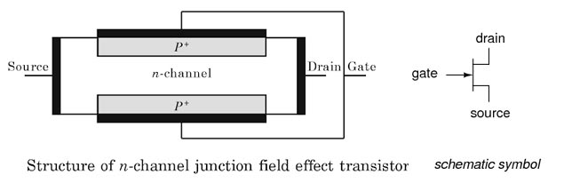
The metallic contacts are made on the ends of the n-type bar to form source and drain terminals. Heavily doped p-type regions are formed (by diffusion, by alloying or by epitaxy) on both sides of the n-type bar. These regions are called gate. Metallic contacts are made over the gate region and are internally connected to form the gate terminal
Majority carriers of the channel constitute the current in JFET. When a voltage is applied between source and drain, the majority carriers flow from source to drain. This current is called drain current. The drain current depends not only on drain-source voltage but also on the gate voltage. In JFET operation, the gate channel p-n junction is reverse biased. So only a small reverse source current flows into the gate. This explains the reason for high input impedance for JFET.
Advantages of FET
The FET has several advantages over the BJTs:
- FET has high input resistance (of the order of 100 MΩ forJFET and 10-10– 1015 for MOSFET so, little input power is required, while transistor has very low input resistance.
- The FET is Less noisy than the bipolar transistor. It is, therefore, used in front ends of FM tuner for the quiet reception.
- It exhibits no offset voltage at zero drain cement, hence makes an excellent signal chopper.
- FETs are thermally more stable than bipolar transistors.
- FETs have smaller size and are simpler to fabricate. Hence, these are incorporated in integrated circuits whereas bipolar transistor is cheaper and offer a large range of choice and are used in discrete circuits.
- FET has the negative temperature coefficient of resistance and, therefore, has better thermal stability whereas BIT has a positive temperature coefficient at high current level. It means in BJT collector current increases with the increase in temperature. This characteristic leads the BJT to thermal breakdown.
- FET has high power gain and, therefore, the necessity of employing driver stages is eliminated.
- FET exhibits no offset voltage at zero drain current and, therefore, makes an excellent signal chopper.
- FET has square law characteristics and, therefore, it is very useful in the tuners of radio and TV receivers.
- FET has the high-frequency response.
Disadvantages of FET
Field effect transistor exhibit following drawbacks:
- Its relative small gain-bandwidth product in comparison with that of a conventional transistor.
- Greater susceptibility to damage in its handling.
- FET has low voltage gains because of small transconductance.
Ques 6 (b). Explain clearly how a fuse rating is selected for the following
- Lightning Circuit
- Power Circuit
Ans:
Fuse:
Fuse is the current interrupting device which breaks or open the circuit (in which it is inserted) by fusing the elements when the current in the circuit exceeds a certain value.
Fuse is a simplest and cheapest device used for interrupting an electrical circuit under the condition of short-circuiting, or excessive overload, current magnitudes.
It is used for Overload and for short-circuit protection in high voltage (upto 66 kV) and for low Voltage (upto 120 V – 240 V) installations/circuits.
The action of a fuse is based upon the heating effect of the electric current. In normal Operating conditions, when the current flowing through the circuit is within the safe limits, the heat developed in the fuse elements carrying this current is readily dissipated into the surrounding air, therefore, fuse elements remain at a temperature below its melting point.
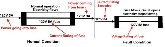
However, when some fault, such as short-circuit occurs or when the load is connected in a circuit its given capacity, the current exceeds the limiting value, the heat generated due to this excessive current cannot be dissipated fast enough and the fusible elements get heated, melts and break the circuit.
Two major classifications of fuses exist:
- Self-resetting fuses
- Non-resettable fuses.
Self-resetting fuses are used in applications where fuse replacement is not possible; this can include aerospace, military, or nuclear equipment. Self-resetting fuses can utilize conductive polymers or thermo-plastic elements such as a polymeric positive temperature coefficient (PPTC) thermistor element. The value of a self-resetting fuse is the element restores to its original state after the electrical over-current (EOC) event has cleared.
Non-resettable fuses are more commonly used where the fuse element is destructive and needs to be replaced after initiation. Non-resettable fuses typically consist of a metallic element which melts during EOC events. Whether its lightning circuit or power circuit the fuse rating is selected on the following bases.
Electrical characteristic parameters of fuse elements are:
- Rated current IN
- Speed
- I2t value
- Breaking capacity
- Rated voltage
- Voltage drop
- Temperature de-rating.
Rated Current
This electrical parameter is the current rating for the maximum current for the fuse during normal operation. This current magnitude is the allowed current magnitude without interruption to the component or system.
Speed
This electrical parameter is the operation time of the fuse structure. Fuses are classified as the slow blow, fast blow, ultra-fast blow, and time-delay. For semiconductor and low voltage applications, it is important to use fast blow or ultra-fast blow fuse elements. With fuses, the fuse speed is a function of the current magnitude.
I2t Value
This parameter is associated with the energy utilized by the fuse to clear the electrical overcurrent (EOC) event. There are two parameters of interest; the melting I2t parameter and the clearing I2t. The melting I2t parameter is associated with the amount of energy to melt the fuse element. The clearing I2t is the amount of energy that is allowed through the fuse to clear the EOC (Electrical Over-current) fault event.
Breaking Capacity
The breaking capacity is associated with the maximum current level that can be addressed by the fuse element.
Rated Voltage
The rated voltage is the maximum voltage that a fuse can sustain in an open circuit. Since the electrode spacings in the fuse have a finite distance, if the voltage is significantly high the failed fuse can still only handle a certain voltage magnitude. The rated voltage must be greater than the maximum applied voltage in the circuit.
Voltage Drop
The fuse element has a series resistance. This series resistance introduces a voltage drop in the circuit. This is a larger issue with low voltage semiconductor-based systems.
Temperature De-rating
The fuse element is typically a metal element, whose resistance is a function of the ambient temperature. The ambient temperature (with no current applied) can influence the electrical characteristics and change the allowed current level. At low temperatures, the current can be increased, and at high temperatures, the fuse must be derated for the temperature change.
Domestic consumers generally receive their supply at 230 V single phase, from the supply company, although in areas where electric space heating is employed a second or third phase may be supplied. Each final circuit must be controlled by a protective device rated at a suitable level to supply the load of the circuit which it protects. Each final circuit must have its own protective device and the “distribution board” for modem domestic installations is generally a consumer unit containing miniature circuit breakers or fuses.
Usually, there are two separate circuits in a house, the lighting circuit with a 5 A fuse and the power circuit with a 15 A – 30A fuse. The lighting circuit is for low-power appliances, such as electric bulbs, tube lights, fans, radios and so on, which draw small currents. The power circuit is for running high power appliances, such as an electric iron, room heater, electric stove, refrigerator and so on, which require heavy currents.
Lightning Circuit
The figure shows a simple Lightning circuit with two-way switching and with each light having an independent switch. The circuit is a radial circuit with the wires taken to connections at each light from the consumer unit out to the last light on the circuit. The live is not taken directly to the lamp at each light connection but via a switch to control each light independently. The earth is also taken to the switch and connected to the switch box to ensure earth continuity if the switch box should become live.
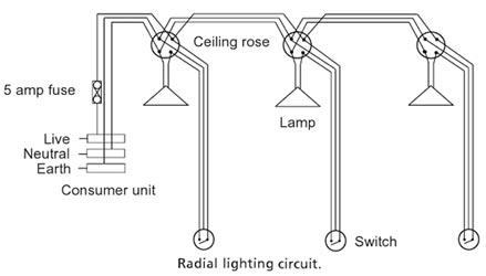
These connections at each light are made to a connection strip on the ceiling rose that is mounted to the ceiling at the light fitting. There are enough connections in the ceiling rose to accommodate two-way switching and multiple lamps on a single switch. Lighting circuits are on 5 amp fuses from the consumer unit with wires of 1 mm2 for PVC-insulated cable.
Power-Circuit
The figure shows a power ring main circuit as the name implies, wiring returning to the consumer unit from the last socket outlet. This means that, unlike the lighting circuit, the first wire does not have to carry the full current of all the appliances and equipment on the circuit. Current able to flow in both directions, the power will balance itself out in the circuit, depending on what equipment is on each socket at any one time.
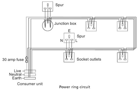
The sizing of the fuse (30 amps) and the wire (2.5 mm2 PVC-insulated cables) is not dependent on the number of sockets but on the probability of the current from equipment associated will a maximum of l00m2 of floor area. Any number of outlets may be installed to ensure the convenience of an outlet for each appliance (or group of equipment as occurs with computer systems and limit trailing wires.
Ques 6 (c). Name the different types of Domestic wiring and compare their performance Briefly
Ans:- Electrical wiring done in residential and commercial buildings to provide power for lights, fasts, pumps and other domestic appliances is known as domestic wiring. There are several wiring systems in practice such as tree system and distribution systems.
Types Of wiring
The following are the different types of wiring system used for domestic electrical installation.
- Cleat wiring system
- Wooden casing-capping wiring system
- PVC wiring or CTS or TRS wiring system
- Lead sheathed wiring system
- Conduit wiring system.
Cleat Wiring
This system of wiring is the cheapest one. This system is used for insulated cables like rubber insulated cable, PVC cable etc. The cables are run over cleats made of porcelain. The cleats are generally in pairs having the bottom and top halves. The bottom half is grooved to receive the wire and the top is for cable grip.
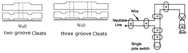
Initially, the bottom and top cleats are fixed on the wall loosely according to the layout. Then the cable is drawn, tensioned and the cleats are tightened by a screw. Cleats are fixed at regular intervals not exceeding 0.6 m Apart. This wiring is suitable for temporary installations where cost is the main criteria.
Advantages of Cleat Wiring:
- It is simple and cheap wiring system
- Most suitable for temporary use i.e. under construction building or army camping
- As the cables and wires of cleat wiring system are in the open environment, Therefore fault in cables can be seen and repair easily.
- Cleat wiring system installation is easy and simple.
- Customization can be easily done in this wiring system e.g. alteration and addition.
- Inspection is easy and simple.
Disadvantages of Cleat Wiring:
- Appearance is not so good.
- Cleat wiring can’t be used for permanent installation because, Sag may be occur after sometime of the usage.
- It is not lasting wire system because of the weather effect, risk of fire and wears & tear.
- It can be only used on 250/440 Volts on low temperature.
- There is always a risk of fire and electric shock.
- it can’t be used in important and sensitive location and places.
- It is not lasting, reliable and sustainable wiring system.
- In this wiring system, the cables and wiring are in the open air, therefore, oil, Steam, humidity, smoke, rain, chemical and acidic effect may damage the cables and wires.
Wooden casing-capping wiring system
This system of wirings shown in Fig It is suitable for low voltage domestic installations where vulcanized rubber insulated cables or plastic insulated cables are used. This wiring system is not used in damp places such as hilly areas as it absorbs moisture.
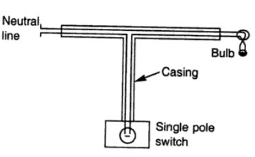
Before the installation of the casing capping, it should be well-varnished from all sides with pure shellac varnish. The casing is fixed by means of flat head wooden screws to wooden plugs with an intent not exceeding 90 cm. After all the wires are laid inside the grooves of the casing, capping should be attached to the casing by rust-resistant screws fixed on edges and screwed to outer walls of the casing at an interval not exceeding 15 cm.
Advantages of Casing Capping Wiring:
- It is cheap wiring system as compared to sheathed and conduit wiring systems.
- It is strong and long-lasting wiring system.
- Customization can be easily done in this wiring system.
- If Phase and the Neutral wire are installed in separate slots, then repairing is easy.
- Stay for a long time in the field due to the strong insulation of capping and casing..
- It stays safe from oil, Steam, smoke, and rain.
- No risk of electric shock due to covered wires and cables in casing & capping.
Disadvantages Casing Capping Wiring:
- There is a high risk of fire in casing & capping wiring system.
- Not suitable in the acidic, alkalies and humidity conditions
- Costly repairing and need more material.
- Material can’t be found easily in the contemporary
PVC wiring or CTS or TRS wiring system:
This system is very widely used.In such a wiring, the wires used are sheathed with the tough rubber of P.V.C. wires and they are clipped on the wooden button with clips. The button is fixed on the wall or ceiling.
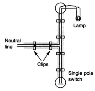
This wiring is suitable for damp climate, but cannot withstand much heat and so is not suitable for places of very hot weather and there is also the danger of mechanical damage and fire hazard. C.T.S. wires are not suitable for outdoor use. Therefore, they should not be exposed to direct sunlight and where there are corrosive acid fumes.
Clips used are of the following two types :
- Link clips
- Joint link clips.
Advantages of CTS or TRS wiring system
- Wiring installation is simple and easy
- cheap as compared to other electrical wiring systems
- The paraphrase is good and beautiful
- Repairing is easy
- strong and long-lasting
- Customization can be easily done in this wiring system.
- less chance of leakage current in batten wiring system
Disadvantages of CTS or TRS wiring system
- Can’t be installed in the humidity, Chemical effects, open and outdoor areas.
- High risk of firs
- Not safe from external wear & tear and weather effects (because, the wires are openly visible to heat, dust, steam, and smoke.
- Heavy wires can’t be used in batten wiring system.
- Only suitable below then 250V.
- Need more cables and wires.
Lead Sheathed Wiring
The wiring is similar to that of CTS but the conductors (two or three) are individually insulated and covered with a common outer lead-aluminum alloy sheath.
The sheath protects the cable against dampness, atmospheric extremities and mechanical damages. The sheath is earthed at every junction to provide a path to ground for the leakage current. They are fixed by means of metal clips on wooden battens. Being very costly these wires are not used nowadays.
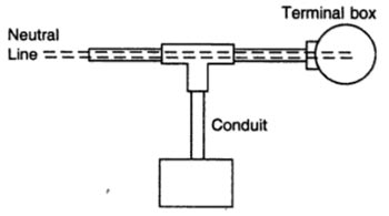
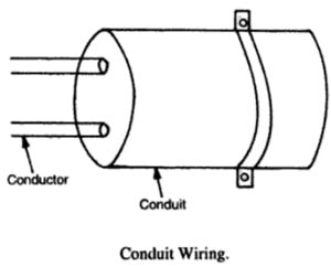
Conduit wiring system
In conduit wiring, wires are carried through steel or iron pipes giving good protection from mechanical injury or fire risks. This system is the best and most desirable system of wiring for workshops and public buildings.
It gives very good appearance when concealed. In this wiring the pipes are cut with the hacksaw and are threaded tee junction box etc. and are then fixed on the walls on wooden gutties or plugs with saddles. Then wires are drawn with the help of fish wire (steel wire).
Nowadays P.V.C. conduit pipes are also available which do not require threading. Jointing is done with a special mode solution. These are flexible and can be bent easily. For concealed wiring, the pipes are directly buried in the wall and roofs and then wires are drawn through them.
Advantages of Conduit Wiring Systems
- It is the safest wiring system (Concealed conduit wring)
- Appearance is very beautiful (in case of concealed conduit wiring)
- No risk of mechanical wear & tear and fire in case of metallic pipes.
- Customization can be easily done according to the future needs.
- Repairing and maintenance are easy.
- There is no risk of damage the cable’s insulation.
- it is safe from corrosion (in case of PVC conduit) and risk of fire.
- It can be used even in humidity, chemical effect and smoky areas.
- No risk of electric shock (In case of proper earthing and grounding of metallic pipes).
- It is reliable and popular wiring system.
- sustainable and long-lasting wiring system.
Disadvantages of Conduit Wiring Systems
- It is expensive wiring system (Due to PVC and Metallic pipes, Additional earthing for metallic pipes Tee(s) and elbows etc.
- Very hard to find the defects in the wiring.
- installation is not easy and simple.
- Risk of Electric shock (In case of metallic pipes without proper earthing system)
- Very complicated to manage additional connection in the future.
Ques 6(d). What are the advantages and disadvantages of electric drive over conventional drive?
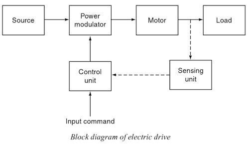
Ans : Motor control is required in large number of industrial and domestic applications such as transportation systems, rolling mills, paper machines, textile mills, machine tools, fans, pumps, robots, and washing machines. Systems employed for motion control are called drives and may employ any of the prime movers.
Drives employing electric motors are known as electric drives.
or
The system which is used for controlling the motion of an electrical machine, such type of system is called an electrical drive.
The electric drive becomes more popular because of its simplicity, reliability, cleanliness, easiness, and smooth control. Both AC and DC motors are used as electric drives however, the AC system is preferred because:
- It is cheaper.
- It can be easily transmitted with low-line losses.
- It can be easy to maintain the voltage at consumer premises within prescribed limits.
- It is possible to increase or decrease the voltage without appreciable loss of power.
In spite of the advantages of AC motor, sometimes DC motor is used because:
- In some processes, such as electrochemical and battery charging, DC is the only type of power that is suitable.
- The speed control of DC motors is easy rather than AC thus, for variable speed applications such as lift and Ward Leonard system, the DC motors are preferred.
- The DC series motor is suited for traction work because of high starting torque.
Advantages of electric drives:
There are a number of inherent advantages that the electric drive possesses over the other forms of conventional drives are:
(1). Easy Control: They have flexible control characteristics. The steady-state and dynamic characteristics of electrical drives can be shaped to satisfy load requirements. Speed can be controlled and, if required, can be controlled within wide limits.
(2) BreakingElectric braking can be employed. Control gear required for speed control, starting and braking are usually simple and easy to operate.
(3) Availability of semiconductor: Availability of semiconductor converters employing thyristors, power transistors, IGBTs and GTOs, linear and digital ICs, and microcomputers have made the control characteristics even more flexible. It is possible to reshape characteristics of drives almost at will to meet load requirements in an optimum manner. Speed and torque and transitions from one mode to another can be controlled smoothly and steplessly. Optimal control strategies can be implemented to achieve high dynamic performance, high efficiency or to minimize a suitable performance index Drives can be provided with automatic fault detection systems. Programmable logic controllers and computers can be employed to automatically control the drive operations in the desired Sequence.
(4). They are available in wide range of torque, speed, and power.
(5) Efficiency: Electric motors have high efficiency, low no-load losses and considerable short time overloading capability. Can be made in the variety of designs to make them compatible with the load. Compared to other prime movers they have the longer life, lower noise, lower maintenance requirements and cleaner operation.
(6) Adaptability: They are adaptable to almost any operating conditions such as explosive and radioactive environment, submerged in liquids, vertical mountings, and so on.
(7) Environment-Friendly: It develops the clean form of energy, as there are no flue gases, etc. Hence it does not pollute the environment.
(8) Ease of Operation: It Can operate in all the four quadrants of the speed-torque plane.
(9) Long-Life: Electric braking gives smooth deceleration and increases the life of the equipment compared to other forms of braking. When regenerative braking is possible, the considerable saving of energy is achieved. These features are not available in other prime movers.
(10) Easy to start: Unlike other prime movers, there is no need to refuel or warm-up the motor. They can be started instantly and can immediately be fully loaded.
They are powered by electrical energy which has a number of advantages over other forms of energy. It can be generated and transported to the desired point economically and efficiently. Conversion of electrical to mechanical energy and vice versa and electrical energy from one form to another can also be done efficiently and economically.
Because of the above advantages, the mechanical energy already available from a nonelectrical prime mover is sometimes first converted into electrical energy by a generator and back to mechanical energy by an electric motor. Electrical link thus provided between the nonelectrical prime mover and the load imparts to the drive flexible control characteristics. Consequently, the load requirements are fully met.
For example, in diesel-electric locomotive and ship, the mechanical energy produced by the diesel engine is converted into electrical energy by an electrical generator and is utilized to drive electric motors which drive locomotive and ship. The operations of generator and motors can be controlled to shape speed-torque curves and other parameters to meet traction or Propulsion requirements in the best possible manner.
Disadvantages of Electric Drive
The two inherent disadvantages of the electrical drive system are :
- It comes to stop as soon as there is failure of electric supply
- It cannot be used at far off places which are not served by electric supply.
However, the above two disadvantages can be overcome by installing diesel-driven D.C. generators and turbine-driven 3-phase alternators which can be used either in the absence of or on the failure of normal electric supply.
For SSC – JE Solved Conventional Paper 2017 Click Here