Ques.31. ______ braking is used where the load on the motor has very high inertia (e.g. in electric trains)?
Coasting
Plugging
Regenerative
Rheostatic
Answer.3.Regenerative
Explanation:-
Regenerative Braking
Regenerative braking occurs whenever the speed of the motor is more than that of the synchronous speed. In this method, the motor runs as a generator, and the load is used to provide the required power to the supply. The main criterion for regenerative braking is that the speed of the motor becomes greater than the synchronous speed. This condition will lead to the motor acting as a generator and the direction of both the current and torque reversing. This method can be utilized where the load on the motor has very high inertia.
When the applied voltage to the motor is less than the back electromotive force (EMF), then both the armature current as well as armature torque reverses and the speed reduces. As generated EMF exceeds the applied voltage, the power transport takes place from the load to the supply.
Ques.32. Form Factor × Peak Factor =?
Maximum Value/Average Value
RMS Value/Average Value
Average Value Maximum Value
Maximum Value/RMS Value
Answer.1.Maximum Value/Average Value
Explanation:-
Form factor: The ratio of r.m.s (or effective) value to average value is the form factor (Kf) of the Waveform. It has used in voltage generation and instrument correction factors.
Peak factor: The ratio of maximum value to the r.m.s value is the peak factor (Kp) of the waveform.
The steady direct current distributes itself uniformly over the whole section of a conductor but the alternating current does not distribute uniformly rather than it tends to concentrate near the surface of a conductor. In fact in the AC system, no current flows through the core and the entire current is concentric at the surface regions. This phenomenon is called skin effect.
The skin effect causes the effective resistance of the conductor to increase with the frequency of the current. The skin effect is due to eddy currents set up by the AC current. The skin effect has practical consequences in the design of radiofrequency and microwave circuits and to some extent in AC electrical power transmission and distribution systems.
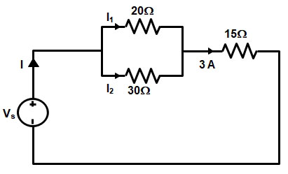
Ques.34. A circuit consists of two parallel resistors, having a resistance of 20Ω and 30Ω respectively connected in series with 15Ω. If the current through the 15Ω resistor is 3A, then find the current through 20Ω and 30Ω resistors respectively?
2A, 1 A
1.2A, 1.8A
1A, 2A
1.8A, 1.2A
Answer.4.1.8A, 1.2A
Explanation:-
Applying current divider rule for the given circuit in 20 ohm resistor
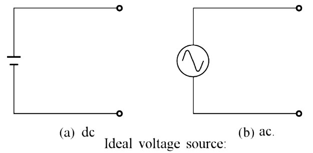
Ques.35. An ideal voltage source is one that ____?
Has infinite internal resistance
Has medium internal resistance
Has zero internal resistance
Supplies constant power
Answer.3.Has zero internal resistance
Explanation:-
An ideal voltage source is the one in which all the three elements R, L, and C, are assumed to be negligible. Thus. the terminal voltage of an ideal voltage source is always equal to its internal e.m.f. Thus a voltage source having internal resistance (or impedance) zero is an ideal voltage source.
An ideal voltage source has the following characteristics:
It is a voltage generator whose output voltage remains absolutely constant whatever be the value of the output current.
It has zero internal resistance so that the voltage drop in the source is zero.
The power drawn by the source is zero.
Ques.36. If the number of poles in an 11 KV transmission line is 80, then how many disc insulators are required?
80
240
160
6
Answer.2.240
Explanation:-
No of disc required for 11 kV transmission line = 1 disc
Since the transmission line is 3-phase, therefore, the number of discs required for a single-pole will be 3.
Total no. of poles = 80
No of disc = 3 × 80 = 240
Ques.37. Which of the following comes under the category of single-phase commutator motors?
Universal motor
Capacitor start motor
Shaded pole motor
Resistance start motor
Answer.1. Universal motor
Explanation:-
The commutator is a feature of d.c motors. But a.c. motors having wound rotor with brushes and commutator arrangements, are called commutator motors that work on single-phase a.c. supply. The commutator arrangement present in these motors is similar to the armature of a d.c. motor.E.g. of single-phase commutator type induction motor is
Repulsion Motor
Repulsion-Induction Motor
AC Series Motor
Universal Motor
Universal motors with brushes and commutators have been designed to operate on either AC or DC power. For this type of motor, the stator’s windings are connected in series with the rotor windings through a commutator. The advantages of universal motors are high starting torque, compact size, and ability to run at high operating speed. The negative aspects include the short lifetime caused by the commutator and brushes and high noise and vibration. This type of motor is often used in applications where the motor only operates intermittently.
Universal motors generally run at high speeds, making them suitable in home appliances (e.g., vacuum cleaners and food mixers) and home power tools (e.g., electric drills) where single-phase wall plug-in power is abundant.
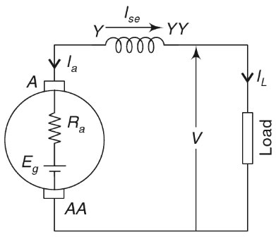
Ques.38. IL = Load Current, then the relation between these currents for a DC series generator is
IL = Ise + Ia
IL ÷ Ise = Ia
IL = Ise = Ia
IL ÷ Ise ÷ Ia
Answer.3. IL = Ise = Ia
Explanation:-
When the field winding is connected in series with the armature winding while supplying the load then the generator is called a series generator.
Current Relations
As all armature, field, and load are in series they carry the same current.
IL = Ise = Ia
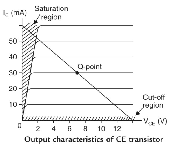
Ques.39. A transistor can be made to operate as a switch by operating it in which of the following regions?
Active region
Active region, saturation region
Active region, cut-off region
Saturation region, cut-off region
Answer.4. Saturation region, cut-off region
Explanation:-
The transistor is a three-terminal device. If it were to be used as an amplifier or a switch, it is supposed to be a two-port device. For a two-port device, four terminals are required. One port is referred to as an input port where the signals are fed into the network and the other port is the output port, where the response of the network is available. So, when a transistor is supposed to be used as a two-port network, one of the terminals of the transistor is made common between input and output.
When both the junctions are forward biased, the transistor is said to be in the saturation region.
When both the junctions are reverse biased, the transistor is in cut off region.
When the emitter junction is forward biased and the collector junction is reverse biased, the transistor operates in active region.
If the circuit uses the Bipolar Transistor as a Switch, then the biasing of the transistor, either NPN or PNP is arranged to operate the transistor at both sides of the I-V characteristics curves. The areas of operation for a transistor switch are known as the Saturation Region and the Cut-off Region.
Ques.40. Which of the following instruments has a uniform scale?
Electrodynamic type
PMMC type
Moving iron type
Dynamometer type
Answer.2. PMMC type
Explanation:-
PMMC instruments are used only to measure DC quantities and not AC quantities. This is because permanent magnets are used for creating magnetic fields. During the positive half, the pointer experiences a force in one direction, and in the negative half the pointer experiences the force in the opposite direction. Due to the inertia of the pointer, it retains it’s zero position.
In the PMMC type instrument, the deflection is directly proportional to the current flowing through the instrument, we get a uniform scale for the instrument. It gives a uniform scale of upto 270° or more.