Ques.21. Hysteresis losses are present in iron core coil when (SSC 2012)
The current in the coil is sinusoidal only
The current in the coil is alternating
The current is unsymmetrical alternation only
The current in the coil is DC only
Answer.2. The current in the coil is alternating
Explanation
Hysteresis losses are also known as Iron Loss or Core Loss and it is always constant.
Hysteresis loss is due to the reversal of magnetization of the transformer core whenever it is subjected to alternating nature of magnetizing force. Whenever the core is subjected to an alternating magnetic field, the domain present in the material will change their orientation after every half cycle. The power consumed by the magnetic domains for changing the orientation after every half cycle is called Hysteresis loss.
Ques.22. Eddy current loss in the ferromagnetic core is proportional to (SSC 2012)
Square of frequency
The square root of frequency
Frequency
Reciprocal of the frequency
Answer.1. Square of frequency
Explanation
The eddy current loss exists due to eddy currents. When the armature core rotates, it cuts the magnetic flux and e.m.f. gets induced in the core. This induced e.m.f. sets up eddy currents which cause power loss. Ibis loss is given by,
Eddy current losses = Ke × Bm2 × f2 × t2
Where Ke = Eddy current constant t = thickness of the core Bm = Maximum flux density f = frequency
∴ Eddy current losses are directly proportional to the square of the frequency.
Ques.23. For welding purpose, the secondary transformer used should be capable of carrying (SSC 2013)
High Voltage, High Current
High voltage, Low Current
Low Voltage, High current
Low Voltage, Low Current
Answer.3. Low voltage, High current
Explanation:
Welding usually requires high current (over 80 amperes) and it can need above 12,000 amperes in spot welding.
A transformer-style welding power supply converts the moderate voltage and moderate current electricity from the utility mains (typically 230 or 115 VAC) into a high current and low voltage supply, typically between 17 and 45 volts and 55 to 590 amperes.
Ques.24. If the frequency of input voltage of a transformer is increased keeping the magnitude of the voltage unchanged, then (SSC 2013)
Both hysteresis loss and eddy current loss in the core will increase
Hysteresis loss will increase but eddy current loss will decrease
Hysteresis loss will Increase but eddy current loss will remain unchanged
Hysteresis loss will decrease but eddy current loss will increase
Answer.3. Hysteresis loss will Increase but eddy current loss will remain unchanged
Explanation:
Eddy Current Loss in the transformer is given as Pe = Kef2B2m
Where Ke = eddy current constant, Bm = Maximum flux density and Bm α (V/f)
For any given voltage, if frequency decreases, Bm increases and if the frequency is increased Bm decreases correspondingly.
Hence the eddy current loss Pe at any given voltage is independent of frequency.
For the fixed magnitude of applied voltage Hysteresis loss is given as
Ph = Kh V1.6 f0.6.
Hence from the above equation, it is clear that with the increase in the frequency Hysteresis losses will increase.
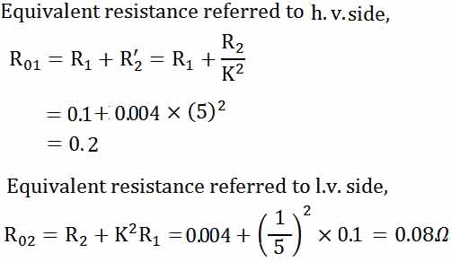
Ques.25. The high-voltage and low-voltage winding resistances of a distribution transformer of 100 kVA, 1100/220 volts, 50 Hz are 0.1 Ω and 0.004 Ω respectively. The equivalent resistances referred to high-voltage side and low-voltage side are respectively (SSC 2013)
2.504 Ω and 0.2 Ω
0.2 Ω and 0.08 Ω
0.10016 Ω and 2.504 Ω
0.008 Ω and 0.10016 Ω
Answer.2. 0.2 Ω and 0.08 Ω
Explanation:
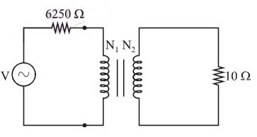
Ques.26. A 10 Ω resistive load is to be impedance matched by a transformer to a source with 6250Ω of internal resistance. The ratio of primary to secondary turns of the transformer should be (SSC 2014)
25
10
15
20
R1 = 6250Ω and R2 = RL = 10Ω
Answer.1. 25
Explanation:-
Then referring the RL =10Ω on the primary side for matching the source impedance
Transformer ratio is given by the general expression
(N2/N1)2 = (V2/V1)
As we know, V = IR
(N2/N1)2 = (I2.R2/I1.R1)
I1 = I2…..(as currents are equal)
(N2/N1)2=(R2/R1)
R2 =R1(N2/N1)2
10 = 6250(N2/N1)2
(N2/N1)2 = 625
(N2/N1) = 25
Ques.27. In which of the following transformers, is the secondary winding always kept closed (SSC 2014)
Current transformer
Potential transformer
Power transformer
Distribution transformer
Answer.1. Current Transformer
Explanation:-
It is important that high alternating-current should not be allowed to pass through normal ammeters and current coils of wattmeters, the current is reduced with the help of a current transformer.
The current transformer is a device having two windings called primary and secondary. It transfers energy from one side to another with a suitable change in the level of current or voltage.
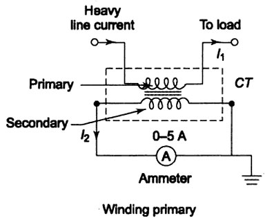
It basically has a primary coil with a few turns having a large cross-sectional area. This primary side is connected in series with the line carrying high current shown in Figure.
On the other hand, the secondary is made up of many turns of fine wire having a rating of 5 A current. This is connected to the coil of a low-range meter.
Current transformers are basically step-up transformers, that is, stepping up the voltage and hence stepping down the current.
The secondary of CT should not be kept open. If it is kept open, the secondary current will be zero and ampere-turns produced by the secondary will be zero.
Since the secondary ampere-turns oppose the primary ampere-turns, the counter MMF will be zero. Hence, unopposed primary produces heavy flux in the core, which causes excessive core losses.
Hence, large emf will be induced in primary and secondary. This will damage the insulation, which is dangerous from the operating point of view.
Ques.28. Low voltage windings are placed nearer to the core in the case of concentric windings because (SSC 2014)
It reduces hysteresis loss
It reduces eddy current loss
It reduces insulation requirement
It reduces leakage fluxes
Answer.3. It reduces insulation requirement
Explanation:-
Why does the low voltage winding of the transformer is placed near to the core?
The LV winding of the Transformer is placed near the core in order to reduce the cost of insulation and the size of the Transformer. The insulation is directly proportional to the voltage so, If the HV winding of the Transformer is placed near the core, the insulation would have to be thicker which leads to higher cost.
Placing the HV winding after the LV winding makes the much lesser thickness of insulation for the HV winding.
Ques.29. If K is the phase-to-phase voltage ratio, then the line-to-line voltage ratio in a 3-phase Y-Δ transformer is (SSC 2014)
K
K /√3
√3K
√3/K
Answer.3.√3K
Explanation:-
The line voltage is given as
VL =√3 × Vphase
Vphase = K ( Given in Question)
∴ VL =√3 K
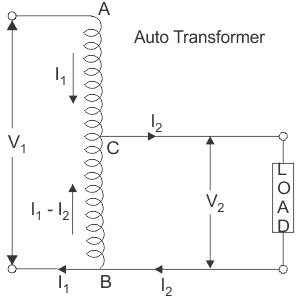
Ques.30. In an auto-transformer of voltage ratio V1/V2, V1 > V2, the fraction of power transferred inductively is proportional to (SSC 2014)
V1 / (V1 +V2 )
V2/V1
(V1 – V2 )/(V1 +V2 )
(V1 – V2 )/V1
Answer.4.(V1 – V2 )/V1
Explanation:-
In an Auto-transfer the power is transferred both inductively and conductively
For inductive power transfer in auto-transformer is Total power input x (V1 -V2)/V1