Ques.41.The current transformer that is used to measure a 100 A current by 5 A ammeter is a ____. (SSC 2016)
Step-up transformer
Step down transformer
Power transformer
Distribution transformer
Answer.1. Step-up transformer
Explanation:-
Instrument transformers are used in conjunction with ammeter and voltmeter to extend the range of meters. In dc circuit shunt and multipliers are used to extend the range of measuring instruments. The shunt is used to extend the range of ammeter whereas multiplier is used to extend the range of voltmeters
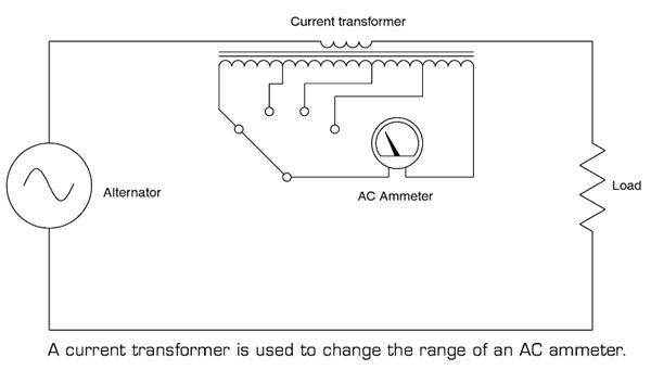
This type of ammeter is shown in Figure. The primary of the transformer is connected in series with the load, and the ammeter is connected to the secondary of the transformer. Notice that the range of the meter is changed by selecting different taps on the secondary of the current transformer. The different taps on the transformer provide different turns-ratios between the primary and secondary of the transformer. The working is explained in detail.
The current transformer is used to step down the current to a lower value so that current can be measured with a normal range ammeter.
The current transformer has a primary coil of one or more turns of thick wire having high cross-sectional area and it is connected in series.
The primary of the current transformer is connected to the load or feeder while the secondary of the current transformer is connected to an ammeter.
The impedance of the primary is very low, and the currents very high. The primary current is dependent on the load on the line rather than the load on the secondary circuit.
The current drawn by the secondary has little effect on line current.
The secondary of the transformer contains many turns of fine wire having a smaller cross-section area and has much higher impedance. If the secondary is not loaded, this transformer acts to step-up the voltage to a dangerous level, due to the high turns ratio. Because of this, a current transformer should always have a short-circuit placed across its secondary winding when connecting or removing any device from its output. By heavily loading the secondary, the high voltage is reduced to the safe level.
The nominal current rating of the secondary winding of the CT is 5A to 1 A.
To illustrate the operation of a current transformer, assume that the current ratio of the primary winding is 100 A. The secondary winding has a standard rating of 5A.
The primary winding consists of three turns of wire, and the secondary winding consists of 60 turns.
The ratio between the primary and the secondary currents is 100 A/5 A, or 20:1
In other words, the primary current is 20 times greater than the secondary current.
Note that the number of turns and the current in the primary and secondary windings are related by an inverse proportion. i.e I1 / I2 = N2 / N1.
By increasing the number of secondary windings, N2, the secondary current can be made much smaller than the current in the primary circuit being measured. In other words, as N2 increases, I2 goes down by a proportional amount.
Ques.42. Which law states that induced e.m.f. and current always opposes the cause producing them? (SSC 2016)
Lenz’s law
Fleming’s law
Faraday’s law
Maxwell’s law
Answer.1. Lenz’s Law
Explanation:-
Lenz’s law provides a way to determine the polarity of an induced emf. As per Faraday’s Law of electromagnetic induction, a current is induced in a conducting loop by the changing magnetic flux. This induced current itself produces a magnetic field and hence a magnetic flux. This magnetic flux may have the same sign as the original magnetic flux or may have the opposite sign. It strengthens the original magnetic flux if it has the same sign or weakens it if opposite sign.
Lenz Law states that “ if there is changing magnetic flux through a loop, then an EMF is “induced” in the loop such that the resulting induced current opposes the change..” In other words, Every effect of induction acts in opposition to the cause that produces it. Here the effect is induced current and cause is changing magnetic flux. That is, the induced current tends to keep the original magnetic flux through the loop from changing. We shall show that this law is a consequence of the law of conservation of energy.
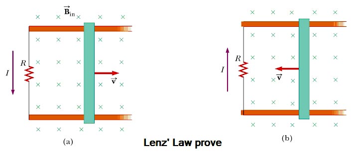
To understand Lenz’s law, consider the example of a bar moving to the right on two parallel rails in the presence of a uniform magnetic field (the external magnetic field, Fig. As the bar moves to the right, the magnetic flux through the area enclosed by the circuit increases with time because of the area increases. Lenz’s law states that the induced current must be directed so that the magnetic field it produces opposes the change in the external magnetic flux. Because the magnetic flux due to an external field directed into the page is increasing, the induced current—if it is to oppose this change—must produce a field directed out of the page. Hence, the induced current must be directed counterclockwise when the bar moves to the right. (Use the right-hand rule to verify this direction.) If the bar is moving to the left as in Figure b, the external magnetic flux through the area enclosed by the loop decreases with time. Because the field is directed into the page, the direction of the induced current must be clockwise if it is to produce a field that also is directed into the page. In either case, the induced current attempts to maintain the original flux through the area enclosed by the closed-loop.
Let’s examine this situation using energy considerations. Suppose the bar is given a slight push to the right. In the preceding analysis, we found that this motion sets up a counterclockwise current in the loop. What happens if we assume the current is clockwise such that the direction of the magnetic force exerted on the bar is to the right? This force would accelerate the rod and increase its velocity, which in turn would cause the area enclosed by the loop to increase more rapidly. The result would be an increase in the induced current, which would cause an increase in the force, which would produce an increase in the current, and so on. In effect, the system would acquire energy with no input of energy. This behavior is clearly inconsistent with all experience and violates the law of conservation of energy. Therefore, the current must be counterclockwise.
Hence Lenz’s Law ensures that, if the electrical energy gained is one unit then the mechanical energy lost is also one unit so that the net energy gain of the wire is zero. Energy is conserved.
Ques.43. For 100 turns as primary, 1000 V, 100 turns secondary transformer will have an output power of? (SSC 2017)
1000 V
500 V
250 V
100 V
Answer.4. 100 V
Explanation:
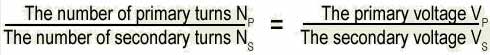
Transformer ratio is given as
= 1000/100 = 1000/Vs
= Vs = 100 Volt
Ques.44. Transformer efficiency compared to other motor is (SSC 2017)
Higher
Remain the same
Lower
None of these
Answer.1. Higher
Explanation:
As the Transformer is a static device, it does not have any rotating parts hence the mechanical losses are absent which increases the efficiency of the transformer.
Ques.45.If there are two 500 W transformer, what will be total input power in Hopkinson test (SSC 2017)
1000 W
More than 1000 W
500 W
None of these
Answer.1. 1000 W
Explanation:
By Hopkinson method, the full load test can be carried out on two identical shunt machine without wasting their output and if two transformers are used then their total power will be added and used as an input power in Hopkinson test.
Ques.46. As per Faraday’s Law of electromagnetic induction, an e.m.f is induced in a conductor whenever it (SSC 2017)
Lies perpendicular to the magnetic flux
Lies in a magnetic field
Cuts magnetic field
Move parallel to the direction of the magnetic field
Answer.3. Cuts magnetic field
Explanation:
Faraday’s Law of electromagnetic induction states that an emf s induced in the conductor whenever it cuts across the lines of force of a magnetic field.
Ques.47. In order to minimize loss due to hysteresis, the magnetic material should have (SSC 2017)
High resistivity
Low Hysteresis co-efficient
Smaller B-H loop area
High retentivity
Answer.3. Smaller B-H loop area
Explanation:
Hysteresis loss is associated with the cyclic magnetization and demagnetization of the material as the magnetic field changes with the sinusoidally varying current.
The hysteresis loss is proportional to the area of the hysteresis loop and therefore in order to reduce the loss the material of the core should have a smaller hysteresis loop area.
Ques.48.The low voltage winding of a 400/230 V, 1-phase 50 Hz transformer is to be connected to a 25 Hz supply. In order to keep the magnetization current at the same level as that for normal 50 Hz, the supply voltage should be (SSC 2017)
230 V
460 V
115 V
65 V
Answer.3. 115 V
Explanation:
To maintain the magnetization current at the same level, the flux should be the same i.e V/f ratio should be same.
V2/F2 = V1/F1
V2 = (230 x 25)/50
= 115 V
Ques.49. Auto-transformer is used in transmission and distributions (SSC 2017)
When the operator is not available
When iron losses are to be reduced
When efficiency consideration can be ignored
When the transformation ratio is small
Answer.4. When the transformation ratio is small
Explanation:
Auto-transformer are generally used for transforming one transformer voltage to another when the ratio is 2:1 or less
Note: An autotransformer is never used as a distribution transformer because the lack of insulation can cause dangerously high voltage in a customer location if the neutral is open.
Ques.50. Determine the maximum flux density (in T) of a material having eddy current coefficient of 2, the thickness of 4 mm, the volume of 20 cu.meter, which is supplied by the frequency of 50 Hz when the material has eddy current loss of 6 W.(SSC 2018 S-1)
2.24
3.34
1.94
1.21
Answer.3. 1.94
Explanation:-
Eddy current losses in the transformer is given by
Eddy current losses = Ke × Bm2 × f2 × V ×t2
Where Ke = Eddy current constant = 2 t = thickness of the core = 4 mm = 4 × 10⁻³ V = Volume of material = 20m3 Bm =Maximum flux density = ? f = frequency = 50 Hz Eddy current losses = 6W