Ques.51. Determine the percentage voltage error of a potential transformer with the system voltage of 11000 V and having a turn’s ratio of 104 if the measured secondary voltage is 98 V. (SSC 2018 S-1)
7.92
5.75
6.25
8.84
Answer.1. 7.92
Explanation:-
System voltage i.e Nominal voltage = 11000 V
V1/V2 = N1/N2
98/V2 = 104
Primary = Turn ratio × Secondary voltage = 98 × 104 = 10192 V
Percentage of error is the Potential error
= (Nominal voltage − Primary voltage)/Primary voltage
(11000 − 10192)/10192
= 7.92%
Ques.52. Scott connections are used for (SSC 2018 S-1)
Single-phase to three-phase transformation
Three Phase to Single Phase transformation
Three-phase to two-phase transformation
Any of the above
Answer.2. Three-phase to two-phase transformation
Explanation
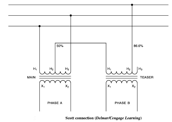
SCOTT CONNECTION
The Scott connection is used to convert three-phase power into two-phase power into two single-phase transformers. The Scott connection is very similar to the T connection that one transformer, called the main transformer, must have a center or 50% tap, and t second or teaser transformer must have an 86.6% tap on the primary side. The difference between the Scott and T connections lies in the connection of the secondary winding (Figure). In the Scott connection, the secondary windings of each transformer provide the phases of a two-phase system. The voltages of the secondary windings are 90° out of phase with each other. The Scott connection is generally used to provide two-phase power for the operation of two-phase motors.
Ques.53. The primary and secondary windings of an Auto-transformer are (SSC 2018 S-1)
Magnetically coupled
Electrically coupled
Both magnetically and electrically coupled
None of these
Answer.3. Both magnetically and electrically coupled
Explanation:-
In the conventional two-winding transformer the primary winding is electrically insulated from the secondary winding. The two windings are coupled together magnetically by a common core. Thus, it is a magnetic induction that is responsible for the energy transfer from the primary to the secondary winding.
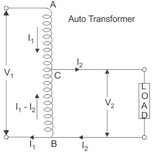
When the two windings of a transformer are also interconnected electrically, it is called an autotransformer. An autotransformer may have a single continuous winding serving as both primary and secondary winding, or it can consist of two or more distinct coils wound on the same magnetic core. In either case, the principle of operation is the same. The direct electrical connection between the windings ensures that a part of the energy is transferred from the primary to the secondary winding by conduction. The magnetic coupling between the windings guarantees that some of the energy is also delivered by induction.
Ques.54. A 40KVA transformer has a core loss of 450 W and a total loss of 800 W. Find the copper loss for Maximum efficiency. (SSC 2018 S-1)
350 W
800 W
450 W
300 W
Answer.3. 450 W
Explanation
It means that the efficiency is maximum at a load when the copper-loss (variable loss) equals the core-loss (constant loss). Thus for maximum efficiency
Ques.55. What is the percentage voltage error of a potential transformer with the system voltage of 11,000 V and having turns ratio of 100, if the measured secondary side voltage is 105 V? (SSC-2018 S-2)
2.75
3.55
4.76
9.09
Answer.3. 4.76
Explanation:-
System voltage i.e Nominal voltage = 11000 V
Voltage Transformation ratio of potential transformer is
V1/V2 = N1/N2
V1/105 = 100
Primary voltage = Turn ratio × Secondary voltage = 105 × 100 = 10500 V
Percentage of error is the Potential error
= (Nominal voltage − Primary voltage)/Primary voltage
(11000 − 10500)/10500
= 4.76%
Ques.56. A transformer (SSC-2018 S-2)
Changes AC to DC
Changes DC to AC
Steps up or down DC voltages & currents
Steps up or down AC voltages & currents
Answer.4. Steps up or down AC voltages & currents
Explanation:-
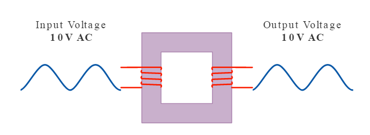
A transformer is a static device which is used to Step up or Step down the AC voltages and current.
If the primary of a transformer is connected to the DC supply, the flux produced in the primary will be of constant magnitude because of DC current. So no EMF will be induced in the primary because emf is induced only when if either the flux is changing or the conductor is moving i.e. the emf will be induced in the winding only when if there is any relative motion between flux and conductor.
So, in this case, the value of the primary current is –
I1 = V1 / R1
The magnitude of this current is very high as E1 is zero and R1 is small. So the transformer can be damaged due to this high current if it is connected to DC supply.
Ques.57. The overall power factor of an ON-Load transformer _____ (SSC-2018 S-2)
Depends on the power factor of the load
Is always Lagging
Is always Unity
Is always Leading
Answer.1. Depends on the power factor of the load
Explanation:-
The overall Power factor of the transformer depending on the power factor of the load.
If the connected load is purely resistive the transformer will work on the unity power factor and there will be no increase in the secondary voltage. E.g Heater coils.
If the connected load is purely capacitive the transformer will work in the leading power factor and there is an increase in secondary voltage. E.g Rectifier
If the connected load is inductive the transformer will work on the lagging power factor and the secondary voltage fall. e.g motor, fans
Ques.58. Breather is provided in a transformer to (SSC-2018 S-3)
Absorb moisture of air during breathing
Provide cold air in the transformer
Absorb moisture from air entering the transformer
Filter the transformer oil
Answer.1. Absorb moisture of air during breathing
Explanation:-
Transformer oil should not be exposed directly to the atmosphere because it may absorb moisture and dust from the environment and may lose its electrical properties in a very short time. To avoid this from happening, a breather is provided. The function of the breather is to prevent the entry of moist air in the transforms tank after its breath out. Even a small amount of moisture absorbed by the oil reduces the insulating properties of the oil considerably.
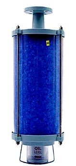
The breather is a cylindrical tube containing oil. silica gel or calcium chloride in different chambers. When the pressure inside the tank reduces due to breath out, it is the breather that absorbs moisture from the air entering the conservator. The entering air is to first pass through the oil which filters the moisture and then through the silica get which further dries the air.
The silica gel when dry is blue in color and when it absorbs moisture, its color becomes somewhat pale Pink. Silica gel in the breather is replaced at certain intervals time.
Ques.59. The primary and secondary windings of a transformer are (SSC-2018 S-3)
Conductively Linked
Inductively Linked
Electrically Linked
Mechanically Linked
Answer.2. Inductively Linked
Explanation:-
A transformer is a static device which converts the alternating current energy from one voltage level to another voltage level.
Transformers are composed of separate coils or windings, having inductive coupling. The primary winding is connected to an ac source. The loads are connected to the secondary winding(s).
One feature of a two-winding transformer is that the primary and secondary are magnetically coupled, yet electrically isolated from each other. The two coils have high mutual inductance. This featured can keep circuits and loads from being directly connected to the power lines, which increases safety.
Note:- Mutual inductance can exist between coils that are not transformer windings but that are close enough for flux linkage to occur.
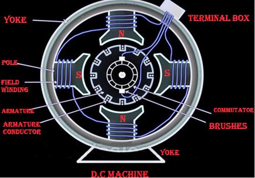
Ques.60. Which of the following is not a part of the transformer? (SSC-2018 S-3)
Commutator
Conservator Tank
Radiator
Tap Changer
Answer.1. Commutator
Explanation
The parts of a transformer include primary and secondary windings, laminated core, Insulating materials, tank, transformer oil, Bucholtz relay, magnetic oil gauge, winding and oil temperature gauges, conservator, breather, bushings, radiators, air vent plugs, drain valve, cooling tubes, and an onload or offload tap changer.
Conservator
The conservator is a metallic tank that provides adequate space for the expansion of oil, whenever the transformer is loaded or during temperature variations. It protects the oil from the deterioration of its insulating property.
Radiators
The radiator units are made from very thin steel sheets of metal for good conduction of heat from the oil to air and are used to take out the heat from the tank. Each radiator will have top and bottom shut-off valves, a top filling plug, a bottom drain plug, lifting lugs, thermometer pockets at the inlet and outlet pipes, air release devices, earthing provisions, filter valves, and all other necessary accessories.
Tap changer
By tap-changing in transformers, it is possible to adjust the output voltage magnitude. It is possible to change taps under load, and such arrangements are called load tap changers (LTC). Tap-changing is usually accomplished using autotransformers.
Note:- Commutator is not part of the transformer.
The commutator is one of very important part of dc machine which rotates with the armature. The function of the commutator is to convert alternating currents induced in the armature conductors into direct currents in the external circuit in case of generator operation. In the case of a dc motor, the function of the commutator is to produce a unidirectional torque. The commutator also helps to keep the magnetic flux stationary in space.
Generally, the alternating voltage is produced in the coil, which is rotating in a magnetic field, but the direct current is required in the external circuit. For this purpose, the commutator is needed. Each commutator segment is connected to the ends of the armature coils. The commutator receives the current from the brushes, which are also placed on the rotating armature.