
Ques.61. Which of the following is TRUE about current transformers? (SSC-2018 S-4)
- It decreases the range of AC ammeter
- It decreases the range of DC ammeter
- It increases the range of AC ammeter
- It increases the range of DC ammeter
Answer.3. It increases the range of AC ammeter Explanation:- Instrument transformers are used in conjunction with ammeter and voltmeter to extend the range of meters. In dc circuit shunt and multipliers are used to extend the range of measuring instruments. The shunt is used to extend the range of ammeter whereas multiplier is used to extend the range of voltmeters This type of ammeter is shown in Figure. The primary of the transformer is connected in series with the load, and the ammeter is connected to the secondary of the transformer. Notice that the range of the meter is changed by selecting different taps on the secondary of the current transformer. The different taps on the transformer provide different turns-ratios between the primary and secondary of the transformer. The working is explained in detail.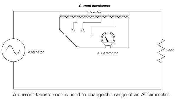
Ques.62. A short-circuit test on a transformer gives (SSC-2018 S-4)
- The copper loss at full load
- The copper loss at any load
- The copper loss at half load
- The copper loss at overload
Answer.2. The copper loss at any load Explanation:- Short circuit test or Impedance test is performed to determine Normally the short circuit test is performed on HV winding by short-circuiting the LV winding because if we perform a test on low voltage side a very high current is going to flow so to measure this huge current will need large measuring instrument such as ammeter. Therefore, the TEST of the short circuit is done in the high voltage side, which equivalently meant low current(a transformer is a constant power device). So the maximum current won’t be more than some 5-50 ampere and can be easily measured. The SC test can be done on either side and will be reflecting the same results, but it is always recommended to work safely, thus shorting the HV side, is the safest way. With one winding short-circuited, typically 10% of rated voltage on the other winding is sufficient to establish a rated full load current. For convenience, we will short the secondary winding, take measurements in the primary winding and refer to the secondary quantities as appropriate. Measure: Vsc short-circuit primary voltage { Very low as compared to the rated voltage Isc short-circuit primary (rated) current { comparable to full load current} Psc short-circuits power (measured with a wattmeter). The short circuit voltage is very low as compared to the rated voltage so if the voltage is very low the loss related to the voltage i.e core loss will also be very less. Hence the core loss is neglected in the short circuit test. Since the high current is passing through the winding, therefore, wattmeter will only read the copper loss. For SC test Power Losses Psc = I2ScRs Where I2Sc = Short circuit current RS = Secondary winding resistance Impedance Zs = VSc ⁄ ISc The copper losses depend upon the loading conditions of the transformers. The copper losses depend on the magnitude of the current flowing through the windings. As the load on the transformer is not constant, the copper loss is called a variable loss If the current through the windings is full load current, we get copper losses at full load. If the load on the transformer is half then we get copper losses at half load which is less than full load copper losses. Thus copper losses are called variable losses. Therefore we can determine copper loss at any load.
⇒ Copper loss at any load
⇒ Equivalent impedance (Zo1 or Zo2)
⇒ Leakage reactance (Xo1 or Xo2)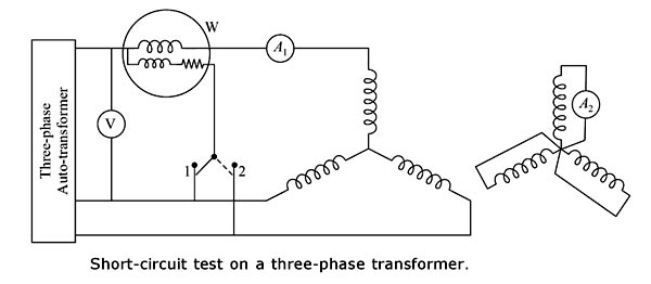
Ques.63. A step-up transformer increases (SSC-2018 S-4)
- Power
- Voltage
- Frequency
- Current
Answer.2. Voltage Explanation:- When the secondary voltage is greater than the primary voltage it is called as a step-up transformer. The function of the step-up transformer is to increase the voltage level. On a step-up transformer, there are more turns on the secondary coil than the primary coil.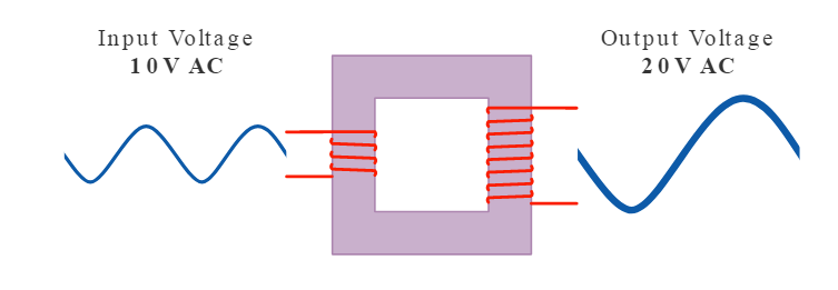
Ques.64. Transformer oil is used as (SSC-2018 S-5)
- An insulator
- A coolant
- Both insulator & coolant
- Inert Medium
Answer.3. Both insulator & coolant Explanation Transformer oil is used in the oil-filled transformer and in some other systems such as high voltage capacitors, fluorescent lamp ballasts, circuit breaker etc. Transformers generate a lot of heat in dropping high voltage to low voltage. The heat has to be removed or the copper will melt and electrical contact will be lost. In comes oil. Oil has a very good heat transfer coefficient (removes heat easily), does not conduct electricity at all (so electrical shorts won’t occur), and is selected to have a high boiling point, so it remains a liquid inside the transformer. It is also very chemically stable, so there is no breakdown over time. There are two main functions of the transformer oil:- The transformer oil should possess the following properties:
Ques.65. Which is to be short-circuited on performing short circuit test on a transformer? (SSC-2018 S-5)
- Low voltage side
- High voltage side
- Primary side
- Secondary side
Answer.1. Low voltage side Explanation Short circuit test or Impedance test is performed to determine Normally the short circuit test is performed on HV winding by short-circuiting the LV winding because if we perform a test on low voltage side a very high current is going to flow so to measure this huge current will need large measuring instrument such as ammeter. Therefore, the TEST of the short circuit is done in the high voltage side, which equivalently meant low current(a transformer is a constant power device). So the maximum current won’t be more than some 5-50 ampere and can be easily measured. The SC test can be done on either side and will be reflecting the same results, but it is always recommended to work safely, thus shorting the LV side, is the safest way. Note that the voltage required to pass the rated current is about 5 to 10% of rated voltage. Let explain it with an example: Consider a 22 kVA, 11 kV/220 V, single-phase transformer on which a short circuit test is to be performed. The rated currents on HV and LV sides are: 22000/11000 = 2 A and 22000/220 V = 100 A respectively. If you short the HV side you need to apply about 11 to 22 V to get a current of 100 A on the LV side. So the wiring used should be able to carry this high current. You need an ammeter to measure 100 A. You need a wattmeter with a current coil rated for 100 A and pressure coil rated at around 25 V. (Difficult to get) If you short the LV side you need to apply about 550 to 1100 V to get a current of 2 A on the HV side. You need an ammeter to measure 2 A. You need a wattmeter with a current coil rated for 2 A and pressure coil rated at around 1100 V.
⇒ Copper loss at any load
⇒ Equivalent impedance (Zo1 or Zo2)
⇒ Leakage reactance (Xo1 or Xo2)
Ques.66. A Single-Phase 50Hz transformer has high voltage and low voltage windings of 2200/220 V. What is the Transformation ratio? (SSC-2018 S-5)
- 10
- 1/10
- 1
- None of these
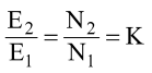
Answer.2.1/10 Explanation The transformer ration K is given as 220/2200 = K K = 1/10
Ques.67. What will be the secondary voltage (in V) of a potential transformer, if the value of system voltage is 11,000 V, the turn’s ratio of the potential transformer is 108 and the percentage voltage error of the transformer is 5%? (SSC-2018 S-6)
- 86.8
- 93.6
- 84.6
- 96.8
Answer.4. 96.8 Explanation System voltage i.e Nominal voltage = 11000 V Transformation ratio of the potential transformer is V1/V2 = N1/N2 V1/V2 = 108 Primary voltage = Turn ratio × Secondary voltage = V2 × 104 = 108V2 Percentage of error is the Potential error = (Nominal voltage − Primary voltage)/Primary voltage 5% = (11000 − 108V2)/108V2 1/20 = (11000 − 108V2)/108V2 108V2 = 220000 − 2160V2 2268V2 = 220000 V2 = 97 V
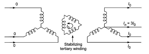
Ques.68. In which transformer, the tertiary winding is used (SSC-2018 S-6)
- Star – Delta
- Star – Star
- Delta – Delta
- Delta – Star
Answer.2. Star – Star Explanation In addition to primary and secondary windings, the transformers may be constructed with Me third winding. This winding is called the tertiary winding. The normal two winding transformers can be converted into three winding transformers with an additional secondary winding having the number of turns as per the requirements. The tertiary winding has the low-voltage rating whereas the primary has the highest voltage rating. The kVA ratings in three-phase transformers are unequal, whereas it is equal in two-winding transformers. The chief advantage of tertiary winding is that it reduces the imbalance of the primary and secondary and hence the secondary load imbalance is distributed more evenly among the primary phases. This is because when the primaries and secondaries are star-connected and the load is unbalanced, this reflects in unbalanced primary currents and the increased circulating current is reduced in tertiary windings. The figure shows the schematic diagram of a three-winding transformer having the primary (N1), secondary (N2) and tertiary (N3) Stabilization Due to Tertiary Winding Advantages of Three winding transformer The disadvantage of a three winding transformer is its construction is a little complicated as compared to the normal two winding transformers. A separate third winding is required to be placed which requires more copper and hence the cost of three winding transformers is obviously more. The core of the transformer has to carry three windings instead of two as in the case of normal two winding transformers.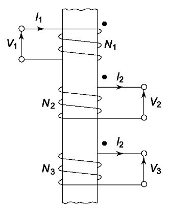
Ques.69. The secondary winding of an auto-transformer is also called (SSC-2018 S-6)
- Compensating winding
- Common Winding
- Tertiary winding
- Damping Winding
Answer.2. Common Winding Explanation Normal transformers have two winding placed on two different sides i.e. primary and secondary. In Auto Transformer, one single winding is used as primary winding as well as secondary winding i.e primary and secondary shares the common single winding. The primary is electrically connected to the secondary, as well as magnetically coupled to it. Auto transformers are often used to step up or step down voltages up to 240 V range. An autotransformer has a single winding with two end terminals and always having one terminal in common with the primary voltage. The primary voltage is applied across two of the terminals, and the secondary voltage is taken from two terminals. The autotransformer develops a voltage in proportion to its number of turns since the volts-per-turn is the same in both windings. In an auto-transformer part of the current flows directly from the input to the output and the remaining part is obtained by transformer action, therefore, an auto transformer work a the voltage regulator.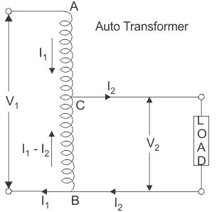
Ques.70. The no-load current in a transformer is (SSC-2018 S-6)
- Sinusoidal
- Non-Sinusoidal
- Trapezoidal
- Stepped
Answer.2. Non-Sinusoidal Explanation When the ac power source is connected to a transformer, a current flows in the primary winding, even when the secondary winding is open-circuited. This is the current required to produce the flux in the ferromagnetic core. The no-load current lc, taken by the primary consists of two components: A reactive or magnetizing component, “Im“ responsible for producing flux in the core An active or energy component, Ie which supplies the hysteresis and eddy current losses taking place in the core and I2R1 loss taking place in the primary winding. The I2R1 loss in the primary winding at no-load is very small and can be neglected for all practical purposes. The no-load current can thus be broken up into its two components, i.e. (a) the magnetizing current,“Im” and (b) the energy current, Ie.. How magnetizing current varies with the applied voltage can be explained as follows: At No- load the induced emf in the primary winding is approximately equal and opposite to the applied voltage. The equation for the induced emf in any winding of a transformer is given by the expression: E = 4.44.φm.f.N V If the frequency of supply φ and the number of turns N are constant then induced emf E is proportional to flux φ. Now flux φ is produced by the magnetizing current Im (a component of the no-load current). The curve giving the relation between B and Im for a magnetic material is known as the magnetizing characteristic. Therefore, in this case, the relation between the induced emf (or terminal voltage) and the magnetizing current will be similar to the magnetizing characteristic of the core material. The core of a transformer is generally made of some ferromagnetic material. In a ferromagnetic material, all the dipoles are aligned parallel. If a small value of the magnetic field is applied, a large value of magnetization is produced. Ferromagnetic material has the permanent dipole moment and the susceptibility is positive. The magnetization in a ferromagnetic material is non-linear and it becomes saturated if a large value of the magnetic field is applied. When a transformer primary winding is supplied with a sinusoidal alternating voltage with the secondary open-circuited, the current flowing through the primary winding produces an alternating magnetic field which in turn induces an emf in this winding approximately equal and opposite to that of the applied voltage. For this emf to be sinusoidal, the flux must vary sinusoidally with time The magnetic flux is produced by the magnetizing current flowing through the primary. The curve showing the relation between magnetic flux and magnetizing current is called magnetizing characteristics. At time t1 the instantaneous value of the flux is Φ1. At the same time, the corresponding value of the mmf loop is H. From this value the corresponding value of magnetizing current I1 can be obtained. At time t2, the flux has the same value of Φ1, but now the flux starts decreasing. The corresponding values of the mmf and current i.e H2 and I2. In this way, the complete waveform of the magnetizing current can be obtained. The wave shape of the magnetizing current would be sinusoidal if the magnetization curve for the core material was linear. However, due to the nonlinear characteristic of the magnetization curve the wave shape of the magnetizing current is nonsinusoidal. Of course, it is symmetric, but not sinusoidal. It contains a series of odd harmonics including the fundamental waveform. If we analyze by using the Fourier-series method, we mostly find third harmonics. According to Lenz’s law, these harmonic currents try to neutralize the harmonic flux produced by the harmonic currents and make it sinusoidal. In single-phase transformers, harmonics are limited only in the primary circuit because the source impedance is much smaller than the load impedance. Thus, we can say that if the flux is sinusoidal, the magnetizing current contains the harmonics with predominant third harmonic but if the magnetizing current is sinusoidal, the flux and hence induced emf will be non-sinusoidal and flat-topped. This can be understood clearly if the transformer is connected to the sinusoidal current source. In this case, the harmonic currents cannot be supplied by the source and the induced emf will be non-sinusoidal and having harmonic voltages. So, when the secondary of the transformer is connected to the load, harmonic currents flow through the load.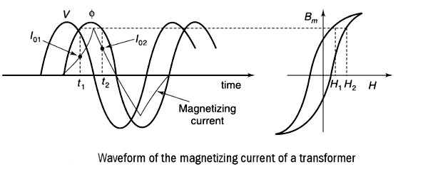
Ques.71. Transformer cooling and insulation oil must be of (SSC-2018 S-6)
- Low viscosity
- High viscosity
- Low BDV
- Low resistivity
Answer.1. Low Viscosity Explanation Transformer oil is used in the oil-filled transformer and in some other systems such as high voltage capacitors, fluorescent lamp ballasts, circuit breaker etc. Transformers generate a lot of heat in dropping high voltage to low voltage. The heat has to be removed or the copper will melt and electrical contact will be lost. Transformer Oil has a very good heat transfer coefficient (removes heat easily), does not conduct electricity at all (so electrical shorts won’t occur), and is selected to have a high boiling point, so it remains a liquid inside the transformer. It is also very chemically stable, so there is no breakdown over time. There are two main functions of the transformer oil:- The transformer oil should possess the following properties:
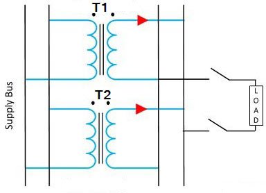
Ques.72. Single Phase transformers can be used in parallel only when their voltages are (SSC-2018 S-6)
- Equal
- Unequal
- Zero
- None of these
Answer.1. Equal Explanation The need for operation of two or more transformers in parallel often arises due to: When two or more transformers run in parallel, they must satisfy the following conditions. Same Voltage Ratio An equal voltage ratio is necessary to avoid a no-load circulating current. Circulating current may be defined as that current which flows in transformers operating in parallel when they do not supply the load. Consider two transformers connected in parallel on their primary sides only. If the voltage readings on the secondaries are not the same, there will be circulating currents between the secondaries when they are connected in parallel. This also creates circulating currents in primaries even when the load is not connected. As the internal impedance of the transformer is small, a small voltage difference may cause the high circulating current which increases copper losses. These circulating currents produce undesirable effects as under: Same percentage impedance The current shared by two transformers running in parallel should be proportional to their MVA rating. And current carried by these transformers is inversely proportional to their internal impedance. Hence the impedance of the transformer running in parallel is inversely proportional to their MVA Rating Each transformer has a particular value of impedance which may be different from the other transformer i.e their resistance to reactance is different. Consider two transformers whose ratings are in the ratio of 4: 1. It is obvious that the first transformer must have one-fourth of the impedance of the second transformer hence the current drawn by the first transformer will be 4 times to the second transformer. Due to the difference in the quality of percentage impedance, there will be the divergence of the phase angle of the two currents so that one transformer will be working with a lower and other with a higher power factor than the combined load. Same Polarity. The polarity of all the transformer running in parallel must be the same. The polarity of transformer refers to the instantaneous direction of Induced EMF in the secondary. If the instantaneous direction of induced secondary EMF in two transformers are opposite to each other when the same input power is fed to both of the transformers, then the transformer is said to be in opposite polarity. If the instantaneous direction of induced secondary EMF in two transformers are sane when the same input power is fed to both of the transformers, then the transformer is said to be in the same polarity. The difference in the polarity causes the huge circulating current that flows in the transformer and even may lead to the dead short circuit.
For SSC JE 2018 SET-1 Electrical paper with complete solution Click Here
For SSC JE 2018 SET-2 Electrical paper with complete solution Click Here
For SSC JE 2018 SET-3 Electrical paper with complete solution Click Here
For SSC JE 2018 SET-4 Electrical paper with complete solution Click Here
For SSC JE 2018 SET-5 Electrical paper with complete solution Click Here
For SSC JE 2017 Electrical paper with complete solution Click Here
For SSC JE 2015 Electrical paper with complete solution Click Here
For SSC JE 2014 (Evening shift) Electrical paper with complete solution Click Here
For SSC JE 2014 (Morning shift) Electrical paper with complete solution Click Here
For SSC JE 2013 Electrical paper with complete solution Click Here
For SSC JE 2012 Electrical paper with complete solution Click Here
For SSC JE 2011 Electrical paper with complete solution Click Here
For SSC JE 2010 Electrical paper with complete solution Click Here
For SSC JE 2009 Electrical paper with complete solution Click Here