SSC JE Electrical Transformer Questions Solved (2009 – 2018) | MES Electrical
Ques 1. If a 500 KVA, 200 Hz transformer is operated at 50 Hz, its KVA rating will be (SSC 2009)
2000 kVA
125 kVA
250 kVA
1000 kVA
Answer.2. 125 kVA
a Explanation
For the same load (constant load), kVA is directly proportional to induced emf. Therefore
S ∝ induced EMF
S ∝ 4.44fNΦ
∴ S ∝ f
S1/S2 = f1/f2
S2 = S1f2/f1
= 500 x 50/200 =125 KVA
Ques 2. The power factor at which the transformer operates is (SSC 2009)
Is unity
is 0.8 lag
Is 0.8 lead
Depends upon the power factor of the load
Answer.4. Depends upon the power factor of the load
Explanation
The operating power factor in the case of a transformer depends upon the load supplied by the transformer. For example, if the transformer is supplying lamp load, the operating power factor is unity, whereas while in most industries, a large percentage of the load consists of an induction motor. These machines operate with lagging power factor hence the power factor of the transformer is lagging, Moreover, the magnitude of the lagging power factor also depends on the nature of the inductive load being supplied by the transformer. Thus the transformer rating is always specified in terms of volt-ampere (VA) or Kilo-Volt-ampere KVA.
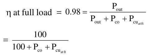
Ques 3. The efficiency of a 100 KVA transformer is 0.98 at full as well as half load. For this transformer at full load the copper loss (SSC 2009)
Is less than the core loss
is equal to core loss
is more than core loss
All the above
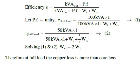
Answer.3. Is more than core loss
Explanation
η at full load = η at half load = 0.98
η at full load of the transformer
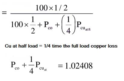
Pco + Pcufl = 2.0408
Where
Pco = Constant Losses
Pcu = Copper losses
⇒ Efficiency η at half load
Solving the equation
Pco = 0.6802 KW
Pcufl = 1.3605 KW
Pcufl > Pco
or
Ques.4. Which of the following will improve the mutual coupling between primary and secondary circuit? (SSC 2009)
Transformer oil of high break down voltage
High reluctance magnetic core
Winding material of high resistivity
Low reluctance magnetic core
Answer.4. Low reluctance magnetic core
Explanation
Magnetic reluctance, or magnetic resistance, is a concept used in the analysis of magnetic circuits. It is analogous to resistance in an electrical circuit, but rather than dissipating electric energy it stores magnetic energy.
Low the reluctance, less the opposition to flux therefore more flux can pass through the transformer core.
Therefore the transformer core is made magnetic steel that has high permeability (low reluctance) to the magnetic flux.
Ques 5. High leakage transformers are of (SSC 2009)
Small voltage-ampere rating
High voltage-ampere rating
High voltage rating
Low voltage rating
Answer.1. Small voltage-ampere rating
Explanation
Most transformers are designed so that as much flux due to the coils is confined to the magnetic circuit as possible, and so that primary and secondary are closely coupled. The aim is to minimize flux leakage to achieve maximum efficiency. However, some transformers are deliberately designed to have a controlled amount of flux leakage because it can provide current limiting in the secondary.
Leakage transformers are transformers where the magnetic flux of the secondary is loosely coupled to the flux of the primary. This loose coupling ensures that the transformer can withstand short circuit conditions. The output and input current of the leakage transformer is low enough to prevent thermal overload under load condition even if the secondary is shorted. Leakage Transformers are also known as Stray field Transformers.
Leakage transformers are used for arc welding and high-voltage discharge lamps (neon lights and cold cathode fluorescent lamps, which are series-connected up to 7.5 kV AC). They act as both voltage transformer and magnetic ballast. Other applications are short-circuit-proof extra-low voltage transformers for toys or doorbell installations.
Ques 6. Bucholtz relay cannot be used on (SSC 2010)
5000 kV transformer
1000 kV transformer
Three-phase transformer
Air-cooled transformer
Answer.4. Air-cooled transformer
Explanation
The Buchholz relay is a gas-operated relay used for the protection of oil-immersed transformers against all the types of internal faults. It is named after its inventor, Buchholz. It is used for the protection of a transformer from the faults occurring inside the transformer, such as impulse breakdown of the insulating oil, insulation failure of turns, etc.
Buchholz relay can be used only in the oil-immersed transformer having a conservative tank. Due to economic considerations, Buchholz relay is not provided for the transformers having below 500 KVA.
Ques.7.A transformer is working at its full load and its efficiency is also maximum. The iron loss is 1000 watts. Then, it copper loss at half of the full load will be (SSC 2010)
250 watt
300 watt
400 watt
500 watt
Answer.1. 250 Watt
Explanation
At maximum efficiency Iron loss = copper loss = 1000 W
The copper loss at the half load will be one-fourth times of full load copper loss. It is given by
Copper loss = X2 × copper loss at full load
Where
X stands for loading condition of the transformer
So for half loading copper loss will be
= (0.5)2 × 1000 w
= 250 W
Ques.8. Distribution transformers are designed to have maximum efficiency nearly at (SSC 2010)
100% of full load
50-70% of full load
25% of full load
10% of full load
Answer.2. 50-70% of full load
Explanation
Distribution transformers are used for lower voltage distribution networks as a means to end-user connectivity. (11kV, 6.6 kV, 3.3 kV, 440V, 230V) and are generally rated less than 200 MVA. Distribution transformers depend on the typical load cycle for which it has to supply power. Definitely Core the design will be done to take care of peak load and as well as all-day-efficiency. It is a bargain between these two points.
The distribution transformer is used for the distribution of electrical energy at low voltage as less than 33KV in industrial purpose and 440v -220v in domestic purpose. It works at low efficiency at 50-70%(due to variation in load), small size, easy in installation, having low magnetic losses & it is not always fully loaded.
Ques.9. A 2 kVA transformer has an iron loss of 150 W and full load copper loss of 250 W. The maximum efficiency of the transformer will occur when the total loss is (SSC 2010)
500 W
400 W
300 W
275 W
Answer.3. 300 W
Explanation
When variable loss becomes equal to the constant loss, efficiency is maximum.
Losses = Pi + Pc
Since copper loss is a variable loss therefore
Losses = Pi + Pi = 2pi
Thus at maximum efficiency of this transformer total loss
= 150 x 2 = 300 W
Ques.10 Potential transformer is used (SSC 2010)
To measure high a.c. voltage
To measure high d.c. voltage
Both (1) and (2)
A protective device in high voltage circuits
Answer.4. A protective devicein high voltage circuits
Explanation
Voltage transformers (VT), also called potential transformers (PT), are a parallel-connected type of instrument transformer. They are used in the electrical power system for stepping down the system voltage to a safe value which can be fed to low ratings meters and relays.