Ques.21. Determine the value of a shunt resistance (in Ohms) required to convert a galvanometer into an ammeter of reading up to15 A. The internal resistance of the galvanometer is 30 Ohms and the value of the current for a full-scale deflection is 0.3A. (SSC-2018 Set-3,5)
0.84
0.74
0.61
0.52
Answer.3. 0.61
Explanation:-
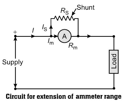
The current range of a DC moving coil ammeter is extended by connecting a shunt Rs (low resistance) across the coil, the circuit as shown in Figure
I = Total current = 15A Im = full-scale deflection current of ammeter = 0.3 Ish = shunt current Rm = resistance of the ammeter = 30Ω Rsh = shunt resistance = ?
Ques.22. Determine the bandwidth (in Hz) of a sine wave that is reproduced by the CRO having a rise time of 70 ms.(SSC-2018 Set-3)
5
10
15
20
Answer.1. 5
Explanation:-
The time required by the waveform to rise from 10 % to 90 % of its peak value is called rise time, denoted as tr
The bandwidth is inversely proportional to rise time and the relation is given by,
Bandwidth = 0.35 ⁄ tr
Where tr = rise time = 70 ms = 70 x 10−3
Bandwidth = 0.35 ⁄ 70 x 10−3
Bandwidth = 5 Hz
Ques.23. Determine the quality factor for Maxwell’s inductance-capacitance bridge is supplied by a frequency of 50 Hz.(SSC-2018 Set-3)
0.16
0.27
0.36
0.47
Answer.4. 0.47
Explanation:-
Note:- You can solve this question in two ways and both the ways are explained in details
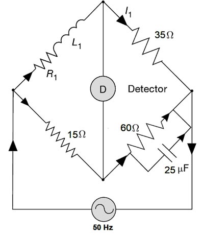
In this bridge, the unknown inductance is measured by comparison with a standard variable capacitance.
The unknown inductor L1 of effective resistance R1 in the branch AB is compared with the standard known variable capacitor C4 on arm CD. The other resistances R2, R3, and R4 are known as non-inductive resistors.
Under the balance condition, the unknown quantities i.e resistor R1 and C1 can be determined by the
R1 = R2 × R3 ⁄ R4
&
L1 = C4 × R2 × R3
Here
R2 = 15 Ω
R3 = 35 Ω
R4 = 60 Ω
C4 = 25 μF
Hence the value of R1 will be
R1 = 15 × 35 ⁄ 60
R1 = 8.75 Ω
&
L1 = 25 × 10−6 × 15 × 35
L1 = 13.125 × 10⁻³
In the Maxwell’s Inductance-Capacitance Bridge, Q-factor or the quality factor of the inductor under measurement can be found at balance condition to be
Q = ωL1/R1
or
Q = ωC4 R4
where ω = 2πf = 2 × 3.14 × 50 = 314
Q = 314 × 13.125 × 10−3 ⁄ 8.75
Q = 0.471
or
Q = 314 × 25 × 10−6 × 60
Q = 0.471
Ques.24. What will be the deflection (in rad) of a moving iron instrument, when the inductance of the moving iron instrument is (20 + 4θ) μH, where θ is the deflection in radian from zero position and the deflection current is 5A? Assuming spring constant k = 10 × 10−6 Nm/rad.(SSC-2018 Set-3)
5
10
15
20
Answer.1. 5
Explanation:-
The deflection in the moving iron instrument is given as
Ques.25. Determine the value of the unknown capacitance Cx ( in μF) for the circuit given below, when no current flows through the detector (D). (SSC-2018 Set-3)
20
40
30
80
Answer.3. 30
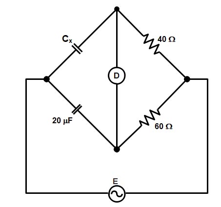
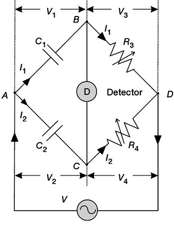
The bridge given in the above question is De Sauty’s Bridge. This is the simplest method of finding out the value of an unknown capacitor in terms of a known standard capacitor. Configuration and phasor diagram of a De Sauty’s bridge under-balanced condition is shown in Figure
The unknown capacitor C1 in the branch AB is compared with the standard known standard capacitor C2 on arm AC. The bridge can be balanced by varying either of the non-inductive resistors R3 or R4.
At Under-balanced condition, since no current flows through the detector, nodes B and C are at the same potentials i.e. V1 = V2 and V3 = V4.
C1 = C2 × R4 ⁄ R3
C1 = ?
C2 = 20μF = 20 × 10−6 F
R3 = 40 ohms
R4 = 60 ohms
Now putting the value of capacitor and Resistor we get
C1 = 20 × 10−6 × 60 ⁄ 40
C1 = 30μF
Ques.26. Which of the following is a type of recording instrument? (SSC-2018 Set-4)
Ammeter
Megger
X-Y Plotter
Voltmeter
Answer.3. X-Y Plotter
Explanation:-
Recording instruments: These instruments give a continuous record of the given electrical quantity which is being measured over a specific period.
In such a recording Instruments, the readings are recorded by drawing the graph. The pointer of such instruments is provided with a marker i.e. pen or pencil, which moves on graph paper as per the reading. The X-Y plotter is the best example of such an instrument.
X-Y recorders are used for many measurements and tests as follows:-
Speed/torque measurements of electric motors.
Lift/drag wind-tunnel tests.
Plotting of characteristic curves of vacuum tubes, transistors, rectifiers, zoner diodes, etc.
Measurement of physical quantities, such as force, pressure, temperature, etc.
Regulation curves of the power supply.
Electrical characteristics of materials such as resistance vs. temperature
Characteristics of governors, such as speed vs. load.
Note:- Ammeter, Voltmeter, Meggar all are Indicating Instrument
Ques.27. In the ‘two-wattmeter method’ of power calculation of a 3-phase balanced star connected system, what is the power factor of the system if both the wattmeters show a positive reading? (SSC-2018 Set-4)
0
Greater than 0 but less than 0.5
0.5
Greater than 0.5 but less than 1
Answer.4. Greater than 0.5 but less than 1
Explanation:-
The reading of two wattmeters can be expressed as
W1 = VLILcos(30 + φ) W2 = VLILcos(30 − φ)
(i) When PF is unity ( φ = 0°)
W1 = VLILcos30° W2 = VLILcos30°
Both wattmeters read equal and positive reading i.e upscale reading
(ii) When PF is 0.5 (φ = 60°)
W1 = VLILcos90° = 0 W2 = VLILcos30°
Hence total power is measured by wattmeter W2 alone
(iii) Power Factor Is More Than 0.5 But Less Than One (i.e.,1 > cosφ > 0.5) or 60° > φ > 0°
Under such conditions, the readings of the wattmeter will be
Hence when the power factor is more than 0.5 but less than one, both me wattmeters give positive (upscale) readings. However, wattmeter W1 gives larger reading than wattmeter W2.
Now, total power, P = W1 + W2 = larger reading + smaller readings
(iv) When PF is less than 0.5 but greater than 0 i.e ( 90° > φ > 60°)
The wattmeter W2 reads positive (i.e.upscale) because for the given conditions (i.e. ( 90° > φ > 60°), the phase angle between voltage and current will be less than 90°. However, in wattmeter W1, the phase angle between voltage and current shall be more than 90° and hence the wattmeter gives negative (i.e. downscale) reading.
Wattmeter cannot show a negative reading as it has only a positive scale. An indication of negative reading is that the pointer tries to deflect in a negative direction i.e. to the left of zero. In such case, reading can be converted to positive by interchanging either pressure coil connections or by interchanging current coil connections. Remember that interchanging connections of both the coils will have no effect on wattmeter reading.
(v) When P.F reads zero (φ = 90°)
Such a case occurs when the load consist of pure inductance or pure capacitance
In this condition, the two wattmeter reads equal and opposite i.e W1 + W2 = 0
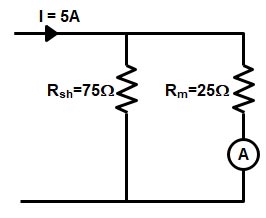
Ques.28. A resistance of 75 Ohms is connected in the shunt of a galvanometer, having an internal resistance of 25 Ohms, to convert it into an ammeter. What is the value of current (in A) flowing through the galvanometer, if the total current in the circuit is 5 A? (SSC-2018 Set-4)
2
2.5
3.65
3.75
Answer.4. 3.75
Explanation:-
Extension of Ammeter Range
The current range of a DC moving coil ammeter is extended by connecting a shunt resistance Rs (low resistance) across the coil, the circuit as shown in Figure
I = Total current = 5A Im = full-scale deflection current of ammeter = ? Ish = shunt current Rm = resistance of the ammeter = 25Ω Rsh = shunt resistance = 75Ω
Ques.29. Which of the following is TRUE about analog multimeter? (SSC-2018 Set-4)
It is a type of absolute instrument
It is a type of indicating instrument
It is a type of recording instrument.
It is a type of integrating instrument.
Answer.2. It is a type of indicating instrument
Explanation:-
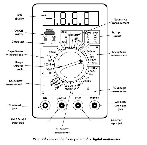
A multimeter is an indicating electronic instrument that can be used for the measurement of three quantities, namely voltage, current, and resistance. This instrument can also be used for both dc and ac voltages and currents. Multimeters are available in both analog and digital form. Although analog multimeters are being replaced by digital multimeters.
Ques.30. The circuit given below is of a circuit _________ bridge. (SSC-2018 Set-4)
Anderson’s
Kelvin’s Double
Maxwell’s inductance
Wheatstone
Answer.3. Maxwell’s inductance
Explanation:-
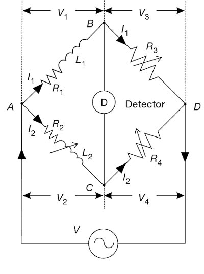
Maxwell Inductance Bridge
This bridge is used to measure the value of an unknown inductance by comparing it with a variable standard self-inductance. The bridge configuration and phasor diagram under-balanced conditions are shown in Figure
The unknown inductor L1 of resistance R1 in the branch AB is compared with the standard known inductor L2 of resistance R2 on arm AC. The inductor L2 is of the same order as the unknown inductor L1. The resistances R1, R2, etc., include, of course, the resistances of contacts and leads in various arms. Branch BD and CD contain known no-inductive resistors R3 and R4respectively.
The bridge is balanced by varying L2 and one of the resistors R3 or R4. Alternatively, R3 and R4 can be kept constant, and the resistance of one of the other two arms can be varied by connecting an additional resistor.
Under the balanced condition, no current flows through the detector. Under such conditions, currents in the arms AB and BD are equal (I1). Similarly, currents in the arms AC and CD are equal (I2). Under the balanced condition, since nodes B and D are at the same potential, voltage drops across arm BD and CD are equal (V3 = V4); similarly, the voltage drop across arms AB and AC are equal (V1 = V2).