
Ques.61. What should be observed when connecting a voltmeter into a DC circuit? (SSC-2016 Set-1)
- RMS
- Resistance
- Polarity
- Power factor
Answer.3. Polarity Explanation:- Precautions to be taken while using a Voltmeter The following precautions must be taken while using a voltmeter: 1) The voltmeter resistance is very high and it should always be connected across the circuit or component whose voltage is to be measured. 2) For using analog voltmeters on DC electricity, it is very important to maintain proper polarity. Most DC power supplies and meters are color-coded to indicate the polarity. Red indicates the positive terminal, and black indicates the negative terminal. The polarities must be observed correctly. The wrong polarities deflect the pointer in the opposite direction against the mechanical stop and this may damage the pointer. If the polarity is reversed when using a digital voltmeter, usually a (- ) minus sign is shown in the display and indicates reversed polarity. However, if you do not reverse the leads, no harm will come to the digital meter. 3) While using the multirange voltmeter, first use the highest range and then decrease the voltage range until the sufficient deflection is obtained. 4) Take care of the loading effect. The effect can be minimized by using high sensitivity voltmeters.
Ques.62. Which of the following capacitors of identical rating will have the smallest dimensions? (SSC-2016 Set-1)
- Ceramic capacitor
- Paper capacitor
- Aluminum foil capacitor
- Mica Capacitor
Answer.1. Ceramic capacitor Explanation:- Electrolytic Capacitors are generally used in DC power supply circuits due to their large capacitance and small size to help reduce the ripple voltage or for coupling and decoupling applications. Electrolytic’s generally come in two basic forms; Aluminium Electrolytic Capacitors and Tantalum Electrolytic Capacitors. The tantalum and electrolytic capacitors have ratings of 6, 10. 12. 15. 20. 25, 35, 50. 75, I00V and higher. Paper capacitors: Paper capacitors use paper as the dielectric. They are made flat strips of metal foil plates separated by a dielectric, which is usually waxed paper. The paper capacitor has values in the picofarad and low microfarad, ranges. The voltage ratings are usually less than 6 V. Paper capacitors arc usually sealed with wax to prevent moisture problems. The voltage rating of capacitors is very important. A typical set of values marked on a capacity might be “10 μF, 50 DCWV.” Such a capacitor h a capacitance of 10 μF and a “dc working voltage” of 50V. This means that a voltage in excess of 50 could damage the plates of the capacitors. Ceramic capacitors: Ceramic capacitors make use of ceramic as the dielectric material. Basically, ceramic materials are fanned from titanium dioxide. Some of the dielectric materials used are barium titanate, magnesium titanic, and zirconium titanate. Ceramic capacitors are produced as tubular, disk, and multilayer (monolithic) capacitors. Disk and tubular ones are inexpensive. Multilayer capacitors are rather expensive but they have small dimensions and low index. The relative permittivity of mica ranges from 3–6(depending upon purity) and the relative permittivity of different types of ceramic ranges from 20–30. Clearly, ceramic capacitors have a higher capacitance. The maximum voltage rating of the ceramic capacitor is 10000 V, while the voltage rating of the mica capacitor is 4000 V.
Ques.63. If the range of an analog transducer is 0 to 10 V, then for a resolution of 5 mV, the bits of ADC will be (SSC-2016, Set-2)
- 8
- 10
- 11
- 12
Answer.3. 11 Explanation:- The output Voltage of ADC is given as; Vout = K × Digital Input Digital Input = Number of steps = ( 2n – 1) VOut = K( 2n – 1) K: resolution = 5mV = 5 × 10⁻³ n: number of bits = ? 10 = 5× 10 – 3 (2n – 1) 2n = 2001 n =11 bits (approximate)
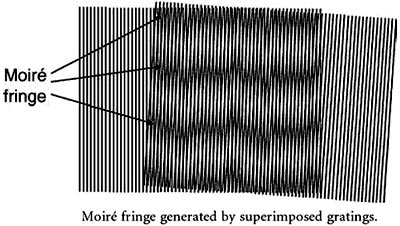
Ques.64. Moire fringes are used to measure rotary displacement along with (SSC-2016, Set-2)
- Contact type encoders only
- Optical encoders only
- Contact type encoders and optical encoders
- None of these
Answer.2. Optical encoders only Explanation:- The word ‘Moire’ is derived from silk fabric which when superimposed on itself exhibit light and dark bands. Optical encoders are common displacement sensors that utilize the Moire effect. Optical encoders are commonly used for measuring angular or linear position, velocity, and directional movement. A typical optical encoder consists of a light source, a disk on which a pattern is etched, a sensing head. The Moire fringe principle has also been used for optical transducers and encoders. The Moire fringe method is basically an optical method of amplifying displacement by using two identical gratings. The opaque lines are at right angles to the length of the grating. When two gratings of the same pitch are mounted face to face with the rulings inclined at an angle θ to each other, a set of dark bands called Moire fringes are obtained. When one grating pattern is moved with respect to the other at right angles to its lines, the Moire fringe pattern travels at right angles to the direction of movement. The measure of movement depends on the relative distance traveled by the gratings. Analysis of the geometric relationship between the Moire fringes and the grating pair enables displacement to be computed. This principle has been applied to measuring length, angle, straightness, and circularity of motion. Example:- The Moire technique is traditionally used for precise displacement measurements. The figure shows the Moire fringe generated by superimposing two gratings. The period of the Moire fringe is much large than that of the gratings. When the angle between the grating lines is increased, the period of the Moir fringe decreases. Translating a grating in a direction perpendicular to the grating lines, the Moire fringe moves in the direction parallel to the grating lines with a magnified displacement. When the two gratings are parallel, the magnification of the displacement is maximized.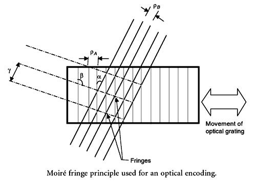
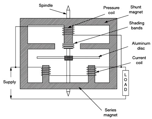
Ques.65. The series magnet of a single-phase Energy meter consists, the coil of (SSC-2016, Set-2)
- Thin wire of few turns
- Thick wire of few turns
- Thick wire of more turns
- Thin wire of more turns
Answer.2. Thick wire of few turns Explanation:- A single-phase energy meter has four essential parts: Operating System The operating system consists of two electromagnets. The cores of these electromagnets are made of silicon steel laminations. The coils of one of these electromagnets (series magnet) are connected in series with the load and are called the current coil. The Current coil consists of few turns of thick wire, connected in series with the load. It carries full load current which depends upon the angle of lag or lead of the load. Therefore the currents in the pressure coil and current coil have a phase difference of nearly 90 degrees. The other electromagnet (shunt magnet) is wound with a coil that is connected across the supply, called the pressure coil. The voltage coil consists of many turns of fine wire encased in plastic, connected in parallel with the load and is highly inductive. This coil is connected in parallel with the supply or load and carries the current proportional to voltage. The current in this coil lags behind the voltage approximately by 90 degrees. The pressure coil, thus, carries a current that is proportional to supply voltage. Shading bands made of copper are provided on the central limb of the shunt magnet. Shading band as will be described later, are used to bring the flux produced by a shunt magnet exactly in quadrature with the applied voltage. The two field fluxes produced by the pressure coil and current coil act on the aluminum disc, induce eddy currents in the disc, and hence the disc rotates due to the interaction of the two fluxes developed. The speed of the disc is proportional to the product of voltage, current and the number of revolutions of the disc (i.e. time). In other words, the disc speed is proportional to the energy consumed by the load. The number of revolutions completed by the disc for one kilowatts hour is called meter constant.
Ques.66. The function of the measurement system is/are (SSC-2016, Set-2)
- Indicating function
- Recording function
- Controlling function
- Indicating, recording and controlling function
Answer.4. Indicating, recording and controlling function Explanation:- Measurement of electrical quantities such as current, voltage, power, and energy are made using instruments called measuring instruments. Such instruments are in use in laboratories, industries, and control stations. Classification of Measuring instruments Measuring instruments can be classified into separate categories based on different criteria. These classifications are useful in knowing the characteristics of instruments and their selection for a particular use. Instruments are classified as active and passive instruments, primary or absolute instruments, secondary or derived instruments, null type, and deflection type instruments, indicating instruments, integrating instruments, recording instruments, analog, and digital instruments, monitoring and control instruments, electromechanical and electronic instruments, etc. Indicating, Recording, and Controlling Function Indicating Function:- Indicating instruments give the output as a function of time through the movement of a pointer over a graduated scale These are, therefore, called analog instruments The deflection type ammeters, voltmeters, and wattmeters in your laboratory are indicating instruments. Voltmeters, ammeters, wattmeters, PMMC, etc. are of indicating type which is extensively used in laboratories and control panels. Recording Function:- Recording instruments create a written record usually on paper of the time-varying quantity. The measurement system carries a pen which is used to record the value of the time-varying quantity on a paper which is driven by a slow-moving motor drive. The curve traced on the paper indicates the actual variation in the value of the quantity being measured. For example, the temperature can be measured and recorded continuously using a recording-type instrument. In the ECG machine, the status of the health of your heart is recorded on a slow-moving paper and can be classified as a recording type instrument. For satisfactory operation of any analog instrument the following systems or function must be present in the instrument: Deflecting System: In order to move the pointer from its zero position on the scale deflecting torque is required. The deflecting torque works on the moving system to which the pointer is attached. Controlling system.: The controlling force is equal and opposite to the deflecting torque in order to make the deflection of the pointer proportional to the magnitude of the quantity to be measured. The controlling force also brings the pointer back to zero position when the force which causes the movement of the pointer is removed. Damping system: Before coming to the rest, the pointer oscillates about the equilibrium position. The damping system provides the damping torque so that the pointer quickly comes to the final steady-state position without any swing or oscillations
Ques.67. In the dynamometer type of wattmeter, which of the coil is split up into two parts? (SSC-2016, Set-2)
- Pressure coil
- Current Coil
- Both the pressure coil and current coil
- None of these
Answer.2. Current Coil Explanation:- An indicating instrument used to measure power in an electric circuit is called wattmeter. Principle The basic principle of dynamometer-type instruments is that when a current-carrying moving coil is placed in the magnetic field produced by the current-carrying fixed coil, a force is exerted on the coil sides of the moving coil and deflection takes place. In other words, when the field produced by the current-carrying moving coil tries to come in line with the field produced by the current-carrying fixed coil a deflecting torque is exerted on the moving system and deflection takes place. Construction The various parts of the electrodynamometer type instrument are Fixed Coils: The dynamometer-type wattmeter essentially consists of two coils called the fixed coil and moving coil. The fixed coil is split into two equal parts that are placed parallel to each other, as shown in Figure. The two fixed coils are air-cored to avoid hysteresis effects when used on AC. The fixed coil is connected in series with the load and carries the circuit current. It is, therefore, called the current coil. The coils are usually varnished. They are clamped in place against the coil supports. This makes the construction rigid. Moving Coil: The moving coil is pivoted between the two parts of the fixed coil and is mounted on the spindle. The moving coil is connected in parallel with the load and carries the current proportional to the voltage applied across the load. It is, therefore, called the potential coil. Generally, a high resistance is connected in series with the moving coil to limit the current through it. By limiting the current, the moving coil is made thin and light in weight which in turn increases the sensitivity of the instrument. The construction of the moving coil is made light as well as rigid. It is air-cored. Controlling: The controlling torque is provided by springs. These springs act as leads to the moving coil.
Ques.68. The current transformer that is used to measure a 100 A current by 5 A ammeter is a _________ (SSC-2016, Set-2)
- Step-up transformer
- Step down transformer
- Power transformer
- Distribution transformer
Answer.1. Step-up transformer Explanation:- Instrument transformers are used in conjunction with ammeter and voltmeter to extend the range of meters. In dc circuit shunt and multipliers are used to extend the range of measuring instruments. The shunt is used to extend the range of ammeter whereas multiplier is used to extend the range of voltmeters This type of ammeter is shown in Figure. The primary of the transformer is connected in series with the load, and the ammeter is connected to the secondary of the transformer. Notice that the range of the meter is changed by selecting different taps on the secondary of the current transformer. The different taps on the transformer provide different turns-ratios between the primary and secondary of the transformer. The working is explained in detail.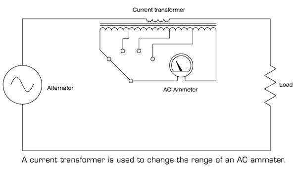
Ques.69. In a flux meter, the controlling torque is (SSC-2016, Set-2)
- Produced by weights attached to the moving coil
- Produced by spring
- Not provided at all
- Provided by crossed coil mechanism
Answer.3. Not provided at all Explanation:- A special ballistic galvanometer with very small controlling torque and high electromagnetic damping is used as a flux meter. It consists; of a small cross-section carrying a coil. The cross-section is suspended in the narrow air gap of the permanent magnet. The cross-section is suspended win the help of spring support and a single thread of silk. The current is injected to the coil through a very thin, annealed silver springs as shown in the figure. The pointer is fitted to the moving system of the fluxmeter and the scale is calibrated in terms of flux turns. Such a flux meter is designed by Grassot and hence it is called Grassot flux mete. The spirals of silver springs keep the controlling torque to the minimum. As controlling torque is minimum, the pointer takes time to come back to the zero position. But readings may be taken by observing the difference in deflection at the beginning and end of the change in flux, without waiting for the pointer to restore its zero position. The fluxmeter is the advanced form of the ballistic galvanometer which has certain advantages like the meter has negligible controlling torque and heavy electromagnetic damping.
Ques.70. Dummy strain gauge is used in conjunction with the main strain gauge to ___ (SSC-2016, Set-2)
- Calibrate the system
- Compensate temperature effects
- Improve sensitivity
- Reduce strain on the gauge
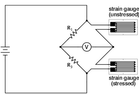
Answer.2. Compensate temperature effects Explanation:- The strain is defined as the deformation of materials caused by the action of stress. A body subjected to external forces is in the condition of both stress and strain. Stress cannot be measured directly. As there is a relationship between stress and strain, the effect of stress can be shown by measurement of the strain. Thus, the stress occurring in a body can be computed if sufficient strain information is available. The measurement helps in knowing better about any structure, whether it is strong enough for the purpose or it may fail in use. The change in resistance of the strain gauge, when subject to strain, is usually converted into a voltage signal by the use of a Wheatstone bridge. A problem that occurs is that the resistance of the strain gauge also changes with temperature, and thus some means of temperature compensation has to be used so that the output of the bridge is only a function of the strain. This can be achieved by placing a dummy strain gauge in an opposite arm of the bridge, that gauge not being subject to any strain but only the temperature. If the temperature changes, both gauge resistances will change by the same percentage, and the bridge’s state of balance will remain unaffected. A popular alternative is to use four active gauges as the arms of the bridge and arrange them so that one pair of opposite gauges is in tension and the other pair in compression. This not only gives temperature compensation; it also gives a much larger output change when strain is applied. 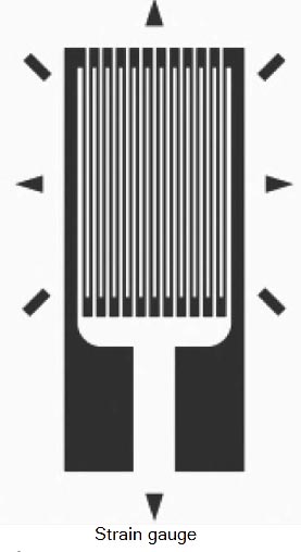
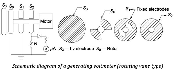
Ques.71. A generating voltmeter uses _______ (SSC-2016, Set-2)
- Constant speed motor
- Variable speed motor
- Variable speed motor with a capacitor
- None of these
Answer.1. Constant speed motor Explanation:- A generating voltmeter, also known as the rotary voltmeter, measures high direct voltages without loading the voltage source and without having any direct connections to the source. This is a variable capacitor electrostatic voltage generator which generates current proportional to the voltage to be measured. The device is driven by an external synchronous or constant speed motor and does not absorb power or energy from the voltage measuring source. For a constant angular frequency is, the current is proportional to the applied voltage V. More often, the generated current is rectified and measured by a moving coil meter. Generating voltmeter can be used for ac voltage measurements also provided the angular frequency ω is the same or equal to half that of the supply frequency. A generating voltmeter with a rotating cylinder consists of two exciting field electrodes and a rotating two-pole armature driven by a synchronous motor at a constant speed n. The ac current flowing between the two halves of the armature is rectified by a commutator. If a time-variant capacitance system can be developed between the high voltage electrode and an earthed electrode, then the current flowing to earth will be a measure of the voltage. Generating voltmeters employ rotating sectors or vanes for variation of capacitance. The figure gives a schematic diagram of a generating voltmeter. The high voltage source is connected to a disc electrode S3 which is kept at a fixed distance on the axis of the other low voltage electrodes S0, S1, and S2. The rotor S0 is driven at a constant speed by a synchronous motor at a suitable speed (1500, 1800, 3000, or 3600 rpm). The rotor vanes of S0 cause the periodic change in capacitance between the insulated disc S2 and the HV electrode S3. The shape and number of the vanes of S0 and S1 are so designed that they produce sinusoidal variation in the capacitance. The generated ac current through the resistance R is rectified and read by a moving coil instrument. An amplifier is needed if the shunt capacitance is large or longer leads are used for connection to rectifier and meter. The instrument is calibrated using a potential divider or sphere gap. The meter scale is linear and its range can be extended by extrapolation. Generating Voltmeter
Working of Generating Voltmeter
Advantages of Generating Voltmeters
Limitations of Generating Voltmeters
Ques.73. Which one of the following is the best method of measurement of the temperature of hot bodies radiating energy in the visible spectrum? (SSC-2016, Set-2)
- Thermocouple
- Thermopile
- Optical pyrometer
- Barometer
Answer.3. Optical pyrometer Explanation:- A pyrometer is a device for measuring very high temperatures and uses the principle that all substances emit radiant energy when hot, the rate of emission depending on their temperature. The measurement of thermal radiation is, therefore, a convenient method of determining the temperature of hot sources and is particularly useful in industrial processes. There are two main types of pyrometer, namely the total radiation pyrometer and the optical pyrometer. Pyrometers are very convenient instruments since they can be used as a safe and comfortable distance from the hot source. Thus applications of pyrometer are found in measuring the temperature of molten metals, the interiors of furnaces or the interiors of volcanoes. Total radiation pyrometers can also be used in conjunction with devices that record and control temperature continuously. Total radiation pyrometers are used to measure temperature in the range of 700°C to 2000°C. Optical pyrometers may be used to measure temperatures up to, and even in excess of, 3000°C. Optical Pyrometer The optical pyrometer is designed to measure temperatures where the peak radiation emission is in the red part of the visible spectrum, that is, where the measured body glows a certain shade of red according to the temperature. The instrument contains a heated tungsten filament within its optical system. The current in the filament is increased until its color is the same as the hot body: under these conditions, the filament apparently disappears when viewed against the background of the hot body. Temperature measurement is therefore obtained in terms of the current flowing in the filament. As the brightness of different materials at any particular temperature varies according to the emissivity of the material, the calibration of the optical pyrometer must be adjusted according to the emissivity of the target.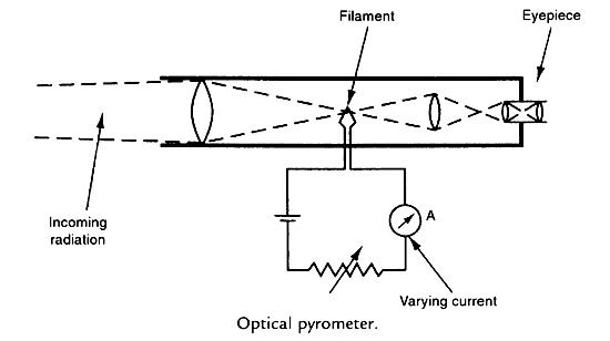
Ques.74. Gauge factor of the strain gauge is defined as the ratio of per unit change in the ____ (SSC-2016, Set-2)
- Conductivity to the per unit change in applied force acting on the element
- Resistance to the per unit change in the length of the element
- Stress to the per unit change in strain of the element
- Current to the per unit change in the length of the element
Answer.2. Resistance to the per unit change in the length of the element Explanation:- The strain gauge is a passive resistive transducer which is based on the principle of conversion of mechanical displacement into the resistance change. The gauge factor is defined as the unit change in resistance per unit change in lengths. It is denoted as K or S. It is also called the sensitivity of the strain gauge. S = (ΔR/R) ⁄ (ΔL/l) Where where S = Gauge factor or sensitivity R = Gauge wire resistance ΔR – Change in wire resistance I = Length of the gauge wire in the unstressed condition Δl = Change in length in the stressed condition
For SSC JE Basic Electrical Questions Solved (2009 – 2018) (Part-3) Click Here
For SSC JE Basic Electrical Questions Solved (2009 – 2018) (Part-2) Click Here
For SSC JE Basic Electrical Questions Solved (2009 – 2018) (Part-1) Click Here
For SSC JE Electrical Transformer Questions Solved (2009 – 2018) Click Here
For SSC JE 2018 SET-1 Electrical paper with complete solution Click Here
For SSC JE 2018 SET-2 Electrical paper with complete solution Click Here
For SSC JE 2018 SET-3 Electrical paper with complete solution Click Here
For SSC JE 2018 SET-4 Electrical paper with complete solution Click Here
For SSC JE 2018 SET-5 Electrical paper with complete solution Click Here