Ques 41. A wattmeter is marked 15 A/30 A, 300 V/600 V and its scale is marked up to 4500 watts. When the meter is connected to 30 A, 600 V, the point indicated 2000 watts. The actual power of the circuit is (SSC-2013)
2000 watts
4000 watts
6000 watts
8000 watts
Answer.4. 8000 watts
Explanation:
Power consumed by wattmeter = CT ratio x PT ratio x VIcosΦ……..1
In the above question
Power consumed by wattmeter = 2000 watts
CT ratio = 15 / 30
PT ratio = 300 / 600
VI = 600 x 30
Putting all the value in equation number 1 we get
2000=(15/30) x (300/600) x 600 x 30 x cosΦ
CosΦ = 0.4444
Power = VI cosΦ = 600 x 30 x 0.4444
Power = 7999.2 ≅ 8000 watts
Ques 42. In a balanced 3-phase system, the current coil of a wattmeter is inserted in line 1 and the potential coil across 2 and 3. If the wattmeter reads 100 W, the reactive power drawn by the 3-phase load is (SSC-2012)
173.2 VAR
50 VAR
100 VAR
141. 4 VAR
Answer.1. 173.2 VAR
Explanation:-
Reactive power drawn by the 3-phase load is
Q = √3 x reading of wattmeter
Q = √3 x 100
173.21 VAR
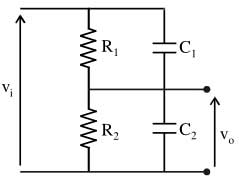
Ques 43. The conditions at which the following potential divider is independent of frequency may be (SSC-2012)
R1/R2 = C1/C2
R1/R2 = C2/C1
R1C1 << 1, R2C2 <<1
R1 + R2 + 1/C1 + 1/C2
ii and iv are true
1 and iii are true
i is true only
ii is true only
Answer.4. ii is true only
Explanation:-
For independent frequency-time constants, RC network must be equal i.e the circuit has an output which is independent of frequency if the low and high-frequency response is identical.
Vo = R1/(R1 + R2) = C2/(C1 + C2)
= R1C1 = R2C2
= R1/R2 = C2/C1
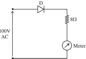
Ques 44. In the circuit forward resistance of the diode D is 2Ω and its reverse resistance is infinitely high. (SSC-2012)
A list consists of meters (List-I) and another list shows, the meter readings (Lis-II)
Which one of the options given here is correct to indicate the type of meter (List-I) and its reading (List-II)
i → (a), (ii) → c
(i) → b, (ii) → (d)
(i) → (a), (ii) → (b)
(i) → (b), (ii) → (a)
Answer.3. (i) → (a), (ii) → (b)
Explanation:-
For PMMC and Hot wire
Given Vrms =100V
Peak voltage Vm = VRMS x √2
= 100 x √2 = 141.42 V
Im = Vm/R = 141.42/(8+2)
Im = 14.14 A
RMS current of half wave rectifier is
Irms = Im/2 = 14.14/2 = 7.07 A →Hot wire
In the most analogous meter movement which employs PMMC deflection system the average current flowing through the meter coil. And the average current for have wave rectified sine wave is
Iavg = Im/π =14.14/π = 4.5A→PMMC
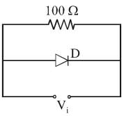
Ques 45. In figure D in an ideal diode. If the RMS value of the input voltage is 50V, then the RMS current through 100 Ω is (SSC-2012)
0.5/√2A
0.25A
0.5A
0.5√2 A
Answer.1. 0.5/√2A
Explanation:-
In the given figure the circuit consists of the single diode, therefore, the Output will be rectified as half wave, hence RMS current of half wave rectifier is
Irms = Im/2
RMS voltage = 50 V
RMS Value of output (Vrms) of Half voltage rectifier
Vrms = Vm/√2
Vm = Vrms x √2 = 50 x √2
Im = Vm/R
= 50√2/100 = 1/√2
Irms = Im/2
= 1/2√2 = 0.5/√2
Ques 46. In a rectifier circuit, the primary function of the filter is to (SSC-2012)
Control the DC level of the output voltage
Remove ripples from the rectified output
Minimize AC input variations
Suppress odd harmonics In the rectifier output
Answer.2. Remove ripples from the rectified output
Explanation:-
We know that rectifiers are used to convert AC to DC, but not a pure DC. The output that is obtained from a rectifier is pulsating in nature, which basically means that it has a certain amount of AC component called the ripple. These ripple components are very much unwanted and undesirable in a rectifier circuit as they reduce the efficiency of AC to DC conversion. So, in order to remove these components, filters are used. A filter ( capacitor-based filter) in a circuit takes this mixed input and produces a pure DC output, bypassing the AC component to earth / neutral.
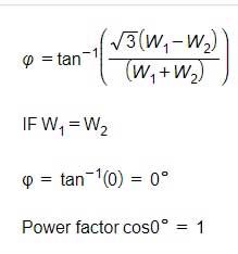
Ques 47. In two wattmeter method of measurement of three-phase power of a balanced load, if both the wattmeters indicate the same reading, then the power factor of the load is (SSC-2011)
Zero
Unity
0.8 lagging
0.8 Leading
Answer.2. Unity
Explanation:-
The power factor of the wattmeter is given as
Second method
Reading of Wattmeter 1 “W1”
W1 = VLIL Cos(30 + Φ)
Reading of Wattmeter 2 “W2”
W2 = VLIL Cos(30 – Φ)
When load P.F cosΦ = 1 then Φ = 0° so that
W1 = W2 = VLIL Cos30
Ques 48. Measurement of ________ is affected by the presence of thermo-emf in the measuring circuit (SSC-2011)
High resistance
Low Resistance
Capacitance
Inductance
Answer.2. Low Resistance
Explanation:-
In the galvanometer circuit, the dissimilar metals come in contact and generate the thermal e.m.f.s. Such thermal e.m.f.s may cause errors while measuring low-value resistances. To prevent this, more sensitive galvanometers having copper coils and copper suspension systems are used.
Ques 49. The response time of an indicating instrument is determined by its (SSC-2011)
Deflecting system
Damping system
Controlling system
Support type of Moving system
Answer.2. Damping system
Explanation:-
The major function of the damping system is to produce a damping force while the moving system is in motion. The damping force should be of such a magnitude that the pointer of the moving system comes to its final steady value quickly without any oscillation.
The response time of an indicating instrument is determined by the Damping system.
If the moving system reaches its final position rapidly and smoothly without oscillations, the instrument is said to be critically damped.
If the moving system oscillates about the final stead, position with a decreasing amplitude and take some time to come to rest then the instrument is said to be underdamped.
The instrument is said to be overdamped if the moving system moves slowly to its find steady position.
In practice, slightly underdamped systems are preferred.
Ques 50. The ratio of the reading of two wattmeters connected to measure active power in a balanced 3-phase load is 2:1. The power factor of the load is (SSC-2011)