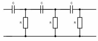
Ques 61. RC network shown in the figure can provide a maximum theoretical phase shift of
90°
180°
270º
360°
Answer.2. 180º
Explanation:
Each RC network Provides a phase shift of 60°. Now there are three RC network, Hence total phase shift will be 180°
Ques 62. Input and output impedance of ideal OPAMP will be?
Zero, Zero
Zero, Infinite
Infinite, Infinite
Infinite, Zero
Answer.4. Infinite, Zero
Explanation:
An ideal opamp has an infinite input impedance. Typically the input impedance of a real op-amp is many 100’s of megaohms or more.
An ideal opamp has an output impedance of zero ohms. Typically the output impedance of a real opamp is on the order of tens of ohms.
Why should op-amp have high input impedance? Because we want to ‘receive’ all the input voltage from the previous circuit. Imagine there was another op-amp driving this op-amp, and this one becomes the load to the previous one.
Why should op-amp have low output impedance? Since we want to ‘transfer’ all the output voltage to the load. The load could be anything the op-amp is driving: a speaker, hard disk motor, digital circuits etc. If the impedance was not ‘zero’, then we would see voltage division at the output and the loads will get ‘weak’ input.
Ques 63. In a BJT with ICBO =1 μA, α = 0.99, the value of ICEO is
0.01 μA
0.1 μA
1 μA
100 μA
Answer.4. 100 μA
Explanation:
ICEO= ICBO/(1 – α)
Where
ICBO = Reverse Leakage Current between Collector and Base while Emitter is Open. (IE=0)
ICEO= Reverse Leakage Current between Collector and Emitter while Base is Open. (IB=0)
In a 3-phase induction motor, a 3- phase supply to the armature produces a rotating magnetic field. This flux is linked to the rotor coils, induces a voltage, and produces a current in the rotor. The current-carrying rotor being placed in a magnetic field experiences a torque and hence begins to rotate.
Ques 65. In a varactor diode using alloy junction, the transition capacitance is proportional to
V2j
1/Vj
1/√Vj
1/√V2j
Answer.3. 1/√Vj
Explanation:
In a varactor diode, junction capacitance is proportional to 1/√Vj
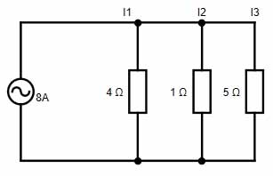
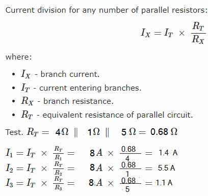
Ques 66. What is I3, I2, I1
5.5, 1.4, 1.1
1.1, 5.5, 1.4
5.5, 1.1, 1.4
1,2,3
Answer.2. 1.1, 5.5, 1.4
Explanation:
The current goes through all 3 resistors, so first we must calculate the total resistance. The formula for any number of resistors in parallel is 1/Rt = 1/R1 + 1/R2 + 1/R3
Ques 67. In a BJT, Ic = 30 mA. If β =100, the base current is approximately equal to
0.03 mA
3000 mA
0.3 mA
30 mA
Answer.3. 0.3 mA
Explanation:
The gain or amplification factor (β) of a transistor is
β = Ic/IB
IB = 30/100
= 0.3 mA
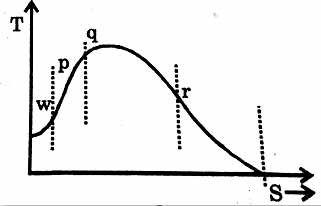
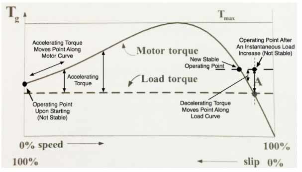
Ques 68. The machine will be stable in the region
W
P
Q
R
Answer.4. R
Explanation:
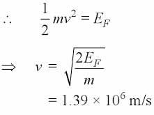
Ques 69. As the Fermi energy of the silver is 8.8 x 10⁻¹⁹ joule, the velocity of the fastest electron in the silver at 0K (Given: Rest mass of electron = 9.1 x 10⁻³¹ Kg).
3.33 x 10⁵ m/s
1.39 x 10⁶ m/s
4.40 x 10⁷ m/s
3 x 10⁸ m/s
Answer.2. 1.39 x 10⁶ m/s
Explanation:
The Fermi energy is the maximum energy that an electron may possess at absolute zero and it is given as
EF = 1/2 mv²
EF = 8.8 x 10⁻¹
m = 9.1 x 10⁻³¹ Kg
Ques 70. KCL is based on the concept of
Charge
Energy
Power
None of these
Answer.1. Charge
Explanation:
This law is also called Kirchhoff’s first law, Kirchhoff’s point rule, or Kirchhoff’s junction rule (or nodal rule).
The principle of conservation of electric charge implies that:
At any node (junction) in an electrical circuit, the sum of currents flowing into that node is equal to the sum of currents flowing out of that node