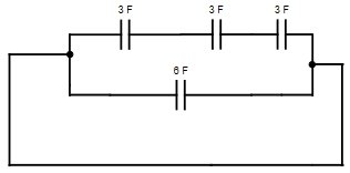
Ques 61. Three 3 μF capacitors are in series. A 6 μF capacitor is in parallel with this series arrangement. The equivalent capacitance of the combination is
7 μF
15 μF
3.6 μF
1 μF
Answer.1. 7 μF
Explanation:
The diagram of the above question will be
Now in capacitor connected in parallel, their equivalent capacitance will be
C = 1/C1 + 1/C2 + 1/C3
= 1/3 +1/3 + 1/3
= 1μF
= 1μF
when the capacitors are connected in series their equivalent capacitance will be
C = C1 + C2
= 1 + 6
=7 μF
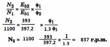
Ques 62. A dc series motor has an armature resistance of 0.06 Ω and a series field resistance of 0.08 Ω. The motor is connected to a 400 V supply. The line current is 20 A when the speed of the machine is 1100 rpm. When the line current is 50 A and the excitation is increased to 30%, the speed of the machine in rpm is
1100 RPM
1003 RPM
837 RPM
938 RPM
Answer.3. 837 RPM
Explanation:
Here
V = 400 V , I1 = 20 A, N1 = 1100
Ra = 0.06 ohm, Rse = 0.08 ohm
I2 = 50 A, N2 =?
Φ2 = 130 % of Φ1 = 1.3 Φ1
While drawing line current of 20 A
Eb1 = V – I1(Ra + Rse)
= 400 – 20(0.06 + 0.08)
= 397. 2 V
While drawing line current of 50 A
Eb2 = V – I2(Ra + Rse)
= 400 – 50(0.06 + 0.08)
= 393 V
We know that
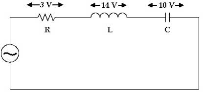
Ques 63. The voltage across R, L, and C are 3 V, 14 V, and 10 V respectively as in the figure. If the voltage source is sinusoidal, then the input voltage (r.m.s) is
10 V
5 V
2.5 V
15 V
Answer.2. 5 V
Explanation:
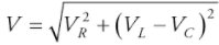
For series RLC circuit the maximum applied voltage is given as
On putting the value
V = 5 v
Ques 64. In the 1-phase series RL circuit fed by a voltage source, the resistance and reactance values are 4 Ω each. In this circuit
The current leads the voltage by 45°
The current lags the voltage by 45°
The current lags the voltage by 60°
None of the above
Answer.2. The current lags the voltage by 45°
Explanation:
The phase difference between applied voltage and current is
tanΦ = XL / R = Lω / R
= 4 Ω / 4Ω
or Φ = π/4 = 45°
Hence the current lags the voltage by 45°
Ques 65. The superposition theorem require as many circuits to be solved as there are
Nodes
Sources
Loops
None of the above
Answer.2. Sources
Explanation:
Superposition is used for circuit analysis methods when we have a circuit with multiple inputs or multiple power sources at least two sources are required which can be a voltage source or current source.
To solve the given circuit using the superposition theorem the contribution of each individual source, all of the other sources first must be “turned off” (set to zero) by
Replacing all other independent voltage sources with a short circuit (thereby eliminating the difference of potential i.e. V=0; internal impedance of the ideal voltage source is zero (short circuit)).
Replacing all other independent current sources with an open circuit (thereby eliminating current i.e. I=0; internal impedance of the ideal current source is infinite (open circuit).
Ques 66. In the squirrel cage induction motor, the rotor conductors are
Open circuited
Short-circuited via end rings
Short-circuited via external resistances
None of the above
Answer.2. Short-circuited via end ring
Explanation:
When 3 phase supply is given to the stator of a 3 phase induction motor, rotating stator flux will be produced, which will induce emf in rotor windings, according to Faraday’s law of electromagnetic induction.
Now if the rotor windings are kept open-circuited, no current will flow in these windings.
Copper bars are short-circuited at both ends via end rings.
Due to short-circuited rotor windings, short circuit rotor currents will flow in them, giving rise to their own magnetic field linking with the stator flux hence the motor start running.
Ques 67. A 3-phase synchronous motor is started by utilizing the torque developed in
The high-speed steam turbine
The damper winding on the rotor
The damper winding on the stator
The low-speed water-turbine
Answer.2. The damper winding on the rotor
Explanation:
Damper windings are windings that are wound to the rotor poles of the machine (winding is similar to that of an induction machine) which helps in two ways.
We all know that a synchronous machine is not self-starting. Thus providing damper windings helps synchronous machines act as an induction motor ( only at starting). Which helps the machine to self-start.
Hunting is a persistent phenomenon when it comes to synchronous machines.
We can reduce hunting to a great extent by damping it. They don’t let the motor oscillate abruptly, they dampen the oscillations thus increasing the stability of the machine.
Ques 68. If the frequency of input voltage of a transformer is increased keeping the magnitude of the voltage unchanged, then
Both hysteresis loss and eddy current loss in the core will increase
Hysteresis loss will increase but eddy current loss will decrease
Hysteresis loss will Increase but eddy current loss will remain unchanged
Hysteresis loss will decrease but eddy current loss will increase
Answer.3. Hysteresis loss will Increase but eddy current loss will remain unchanged
Explanation:
Eddy Current Loss in the transformer is given as
Pe = Kef2B2m
Where Ke = eddy current constant
Bm = Maximum flux density and Bm α (V/f)
For any given voltage, if frequency decreases, Bm increases and if the frequency is increased Bm decreases correspondingly.
Hence the eddy current loss Pe at any given voltage is independent of frequency.
For the fixed magnitude of applied voltage Hysteresis loss is given as
Ph = Kh V1.6f0.6.
Hence from the above equation, it is clear that with the increase in the frequency Hysteresis losses will increase.
Ques 69. Two single-phase ac motors A and B operate from a 1000 V supply. A consumes 2 KW at a power factor of 0.8 (lagging) and B consumes 1 kW at a power factor of 0.5 (lagging). The total current drawn from the supply is approximately