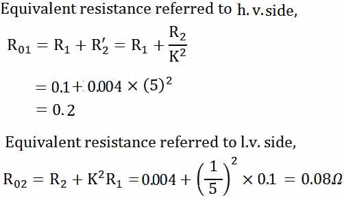
Ques 70. The high-voltage and low-voltage winding resistances of a distribution transformer of 100 kVA, 1100/220 volts, and 50 Hz are 0.1 Ω and 0.004 Ω respectively. The equivalent resistances referred to high-voltage side and low-voltage side are respectively
2.504 Ω and 0.2 Ω
0.2 Ω and 0.08 Ω
0.10016 Ω and 2.504 Ω
0.008 Ω and 0.10016 Ω
Answer.2. 0.2 Ω and 0.08 Ω
Explanation:
Ques 71. A tank circuit consists of
An inductor and a capacitor are connected in series
An inductor and a capacitor are connected in parallel
A pure inductance and a pure capacitance are connected in series
A pure inductance and a pure capacitance are connected in parallel
Answer.4. A pure inductance and a pure capacitance connected in parallel
Explanation:
An LC circuit, also called a resonant circuit, tank circuit, or tuned circuit is an electric circuit consisting of an inductor, represented by the letter L, and a capacitor, represented by the letter C, connected together in Parallel.
Ques 73. The instantaneous power of a 1-phase series circuit supplying R-L load from a sinusoidal voltage source has in each cycle
Negative twice, zero four times
Zero twice, negative once
Negative four times, zero twice
Negative twice, zero once
Answer.1. Negative twice, zero four times
Explanation:
Instantaneous power is the power of the object at any instant of time, in general, it is defined as p(t) = v(t) x i(t)
In a single-phase ac circuit, the instantaneous power to a load is of pulsating nature. Even at the unity power factor, the instantaneous power is always less than the unity
For a sinusoidal signal, the voltage swings through zero volts twice a cycle, so the instantaneous power is zero two times per cycle.
If the load has both resistance and reactance, then the current, and voltage swings through zero twice a cycle, with different phase angle, and thus the instantaneous power will swing through zero 4 times a cycle.
Instantaneous power is positive for one part of the cycle and negative for another part of the cycle if there is both resistance and reactance in the circuit. then there will be one negative for voltage and one negative for current thus instantaneous power will have two negative per cycle for a single-phase R-L series circuit.
Ques 74. In a series R-L-C circuit, the “Q-factor” is given by
1/R√L/C
R√L/C
1/R√C/L
R√C/L
Answer.1. 1/R√L/C
Explanation:
The Q factor is a parameter that describes the resonance behavior of an underdamped harmonic oscillator (resonator).
In an ideal series RLC circuit, and in a tuned radio frequency receiver (TRF) the Q factor is: 1/R√L/C
The larger the series resistance, the lower the Q factor.
Ques 75. In an ac circuit, V = (200 + j40) V and I = (30 – j 10) A. The active and reactive power of the circuit are respectively
6400 W, 800 VAR capacitive
6400 W, 800 VAR inductive
5600 W, 3200 VAR capacitive
6400 W, 3200 VAR inductive
Answer.2. 6400 W, 800 VAR capacitive
Explanation:
Active power = 200 x 30 + 40 x10 =6400 W
Reactive Power = 200 x 10 – 40 x 30 = 800 VAR
Ques 76. Application of Norton’s theorem in a circuit results in
A current source and impedance in parallel
A voltage source and impedance in series
An ideal voltage source
An ideal current source
Answer.1. A current source and an impedance in parallel
Explanation:
Norton’s theorem illustrates that a network consists of several voltage sources, current sources, and resistors with two terminals, which is electrically equivalent to an ideal current source ” INO” and a single parallel resistor, RNO
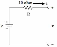
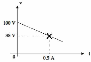
Ques 77. The voltage (v) vs. current (i) curve of the circuit is shown below:
24 Ω
4 Ω
10 Ω
14 Ω
Answer 4. 14 Ω
From the circuit diagram
e = V – 10i
r = e/i
= V/i -10
On differentiating
dr = dv/di -10
= 12/0.5 – 10 = 14 Ω
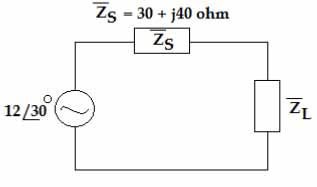
Ques 78. The value of the load impedance ZL for which the load consumes maximum power is
50 Ω at a power factor of 0.6 lead
50 Ω at a power factor of 0.6 lag
30 Ω at a power factor of unity
None of the above
Answer.1. 50 Ω at a power factor of 0.6 lead
Explanation:
For maximum power transfer
ZL = Zs* = 30 – j40
Apparent power
Zs2 = 302 + 402
Zs = 50 Ω
Power factor = Real power/ Apparent power
CosΦ = 30/50 = 0.6 leading
A leading power factor signifies that the load is capacitive, as the load “supplies” reactive power, and therefore the reactive component Q is negative as reactive power is being supplied to the circuit.
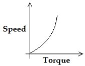
Ques 79. The speed-torque characteristic of a dc series motor operating from a constant voltage supply is
Answer.3.
Explanation:
Speed torque characteristic is also called a mechanical characteristic. From the characteristics of the DC series motor, it can be found that when speed is high, torque is low, and vice versa.
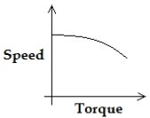
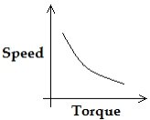
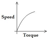
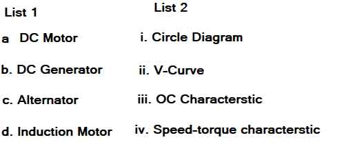
Ques 80. Match List I (Machine) with List-II (graph) and select the appropriate response.
a-(iv), b-(iii), c-(i), d-(ii)
a-(iii), b-(iv), c-(ii), d-(i)
a-(iv), b-(iii), c-(ii), d-(i)
a-(iii), b-(iv), c-(i), d-(ii)
Answer.3. a-(iv), b-(iii), c-(ii), d-(i)
Explanation:
The speed-torque characteristics is graph of DC motor.
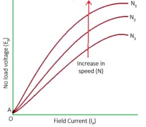
Open circuit characteristic is also known as the magnetic characteristic or no-load saturation characteristic. it’s a graph plotted between emf induced and excitation is given ( field current ) at no load. This gives us an idea of how the dc machine is going to behave in certain field current.
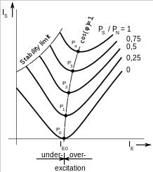
In power engineering & electrical engineering, the V curve is the graph showing the relation of armature current as a function of field current in synchronous machines. The purpose of the curve is to show the variation in the magnitude of the armature current as the excitation voltage of the machine is varied.
The circle diagram is the graphical representation of the performance of the electrical machine[1][2][3] drawn in terms of the locus of the machine’s input voltage and current.[4] The circle diagram can be drawn for alternators, synchronous motors, transformers, and induction motors.