
Ques.21. When the voltage applied to a synchronous motor is increased, which of the following will reduce? (SSC-2018 Set-3)
- Stator Flux
- Pull in Torque
- Pull out Torque
- None of these
Answer.4. None of these Explanation:- Let us know the factors, facts, assumptions that are dependent on supply voltage for the good operation of the synchronous motor. The synchronous motor is a dual-excited constant speed motor, Basically supply voltage is injected such that it produces RMF at specified phase angles wrt to phases in the stator of our motor. As in the case of Induction motors Variation in the frequency of the source will result in the corresponding change in the flux in the air gap. Hence, in order to operate the motor with fairly constant flux in the air gap, it is necessary to vary the magnitude of the applied voltage in the same ratio as the frequency of the supply (i.e V/f should be kept constant) and to keep the excitation current constant. If a synchronous motor is driven by an external power source, and the excitation, or voltage applied to the rotor, is adjusted to a certain value called 100 percent excitation, no current will flow from or to the stator winding. In this case, the voltage generated in the stator windings by the rotor, or back EMF, exactly balances the applied voltage. However, if the excitation is reduced below the 100-percent value, the difference between the back emf and the applied voltage produces a reactive component of current which lags the applied voltage. The machine then acts as an inductance. Similarly, if the excitation is increased above the 100-percent value, the reactive component leads the applied voltage, and the machine acts as a capacitor. This feature of the synchronous motor permits uses of the machine as a power-factor correction device. When so used, it is called as the synchronous condenser. Note:- In most applications, the voltage applied to the synchronous machine cannot be varied. This is true because in most cases the machine is directly connected to the grid and the terminal voltage is therefore fixed.
RMF produces enough constant magnitude flux, Let us assume that initially our synchronous motor was operated at a voltage less than the preset voltage value.
Ques.22. A synchronous motor has a better power factor than an induction motor. This is due to (SSC-2018 Set-3)
- Stator supply is not required to produce the magnetic field
- Synchronous Motor has no Slip
- Mechanical Load on the rotor remain constant
- Synchronous motor has a large air gap
Answer.1. Stator supply is not required to produce the magnetic field Explanation:- A synchronous motor is a machine that converts electric power into mechanical power at a constant speed called synchronous speed. It is a doubly excited machine because its rotor winding is excited by direct current and its stator winding is connected to an A.C supply. Stator: Stator is the stationary part of the machine. The three-phase armature winding is placed in the slots of the stator core and is wound for the same number of poles as the rotor. The stator is excited by a three-phase ac supply as shown in the Figure Rotor: The rotor of the synchronous motor can be of the salient pole or cylindrical pole (Non-salient) type construction. Practically most of the synchronous motor use salient i.e., projected pole type construction, except for exceedingly high-speed machines. The field winding is placed on the rotor and it is excited by a separate dc supply. Although the synchronous motor starts as an induction motor. it does not operate as one. After the armature winding has been used to accelerate the rotor to about 95% of the speed of the rotating magnetic field, direct current is connected to the rotor and the electromagnets lock in step with the rotating field. Notice that the synchronous motor does not depend on the induced voltage from the stator field to produce a magnetic field in the rotor. The magnet field of the rotor is produced by external DC applied to the rotor. This is the reason that the synchronous motor has the ability to operate at the speed of the rotating magnetic field. As the load is added to the motor, the magnetic field of the rotor remains locked with the rotating magnetic field and the rotor contir ues to tuna at the same speed. It should be noted that the changes in the dc field excitation do not affect the motor speed. However, such changes do alter the power factor of a synchronous motor. If all of the resistance of the rheostat is inserted in the field circuit, the field current drops below its normal value. A poor lagging power factor results. If the dc field is weak, the three-phase ac circuit to the stator supplies a magnetizing current to strengthen the field. This magnetizing component lags the voltage by 90 electrical degrees. The magnetizing current becomes a large part of the total current input. This gives rise to a low lagging power factor. If a weak dc field is strengthened, the three-phase ac circuit to the stator supplies less magnetizing current. Because this current component becomes a smaller part of the total current input to the stator winding, the power factor increases. The field strength can be increased until the power factor is unity or 100%. When the power factor reaches unity, the three-phase ac circuit supplies energy current only. The dc field circuit supplies all of the current required to magnetize the motor. The amount of dc field excitation required to obtain a unity power factor is called normal field excitation. The magnetic field of the rotor can be strengthened still more by increasing the dc field current above the normal excitation value. The power factor in this case decreases. The circuit feeding the stator winding delivers a demagnetizing component of current. This current opposes the rotor field and weakens it until it returns to the normal magnetic strength. Hence Higher PF means the low requirement of MMF for energy transfer, hence low magnetizing current requirement. The synchronous machine has separate DC excitation which reduces the machine’s excitation dependency on the mains supply, hence better PF. whereas the Induction motor has no such provisions, hence low Power factor.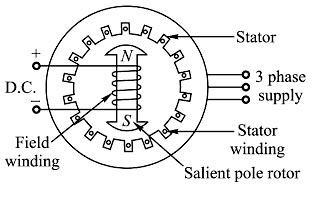
Ques.23. When the field circuit of an unloaded salient pole synchronous motor gets suddenly open circuited, then (SSC-2018 Set-3)
- The Motor Stops
- It runs at a slower speed
- It continues to run at the same speed
- It runs at a very high speed
Answer.1. The motor stops Explanation:- The synchronous motor starts as an induction motor. it does not operate as one. After the armature winding has been used to accelerate the rotor to about 95% of the speed of the rotating magnetic field, direct current is connected to the rotor and the electromagnets lock in step with the rotating field. Notice that the synchronous motor does not depend on the induced voltage from the stator field to produce a magnetic field in the rotor. The magnet field of the rotor is produced by external DC applied to the rotor. To shut down the motor, the field circuit is de-energized by opening the field discharge switch. The field discharge resistor is connected across the field circuit to reduce the induced voltage in the field as the field flux collapses The energy stored in the magnetic field is spent in the resistor, and a lower voltage is induced in the field circuit thus rotating the magnetic field will not develop and the motor will stop. Note:- The synchronous motor either runs on synchronous speed or it will not run at all.
Ques.24. The armature current of a synchronous motor is minimum when operating at (SSC-2018 Set-3)
- Unity Power factor
- 0.707 Power factor lagging
- 0.707 power factor leading
- Zero power factor leading
Answer.1. Unity Power factor Explanation:- The power factor of the synchronous motor can be changed by changing the field current. When the field current is changed, the armature current of the synchronous motor also changes. Now suppose that a synchronous motor is running at no load. If the field current is increased, the armature current la decreased until the armature current becomes the minimum. At this point, the synchronous motor is running at unity power factor. Before this point, the synchronous motor was running at the lagging power factor and the armature current is low lagging. Now if we increase the field current, the armature current increases (high Lagging) and the motor starts operating at a leading power factor. It must be noted that due to the constant load, the cosine component of the armature current, In cosφ always remains constant. The V-curves of a synchronous motor show how armature current varies with its field current when the motor input is kept constant and is so-called because of their shape. The minimum armature current corresponds to the unity power factor.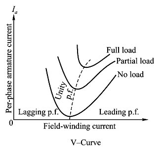
Ques.25. The resultant armature voltage of a synchronous motor is equal to the_______. (SSC-2018 Set-4)
- Vector sum of Eb and V
- Vector difference of Eb and V
- Arithmetic sum of Eb and V
- Arithmetic difference between Eb and V
Answer.2. Vector difference of Eb and V Explanation:- When a dc motor or an induction motor is loaded, the speed of the motor drops. This is because the load torque demand increases than the torque produced by the motor Hence the motor draws more current to produces more torque to satisfy the load but its speed reduces. In case of synchronous motor speed always remains constant equal to the synchronous speed, irrespective of load condition It is interesting to study how synchronous motor reacts to changes in the load condition. In a dc motor, armature develops an emf after motoring action starts which opposes the supply voltage called back emf. Eb. The resultant voltage across the armature is (V – Eb) and it causes an armature current la = (V – Eb) ⁄ Ra to flow where Ra is armature circuit resistance. In case of the synchronous motor also, once the rotor starts rotating at synchronous speed, the stationary stator (armature) conductors cut the flux produced by the rotor. The only difference is the conductor is stationary and flux is rotating. Due to this, there is an induced emf in the stator which according to Lenz’s law opposes the supply voltage. This induced emf is called back emf in case of the synchronous motor. It is denoted as Ebph i.e., back emf per phase. This gets generated as the principle of the alternator and hence alternating in nature. So back emf in case of the synchronous motor depends on the excitation given to the field winding and not on the speed as speed is always constant. The net voltage in the armature (stator) is the vector difference (not arithmetical, as in d.c. motors) of Vph and Ebph. Armature current is obtained by dividing this vector difference of voltages by armature impedance (not resistance as in d.c. machines).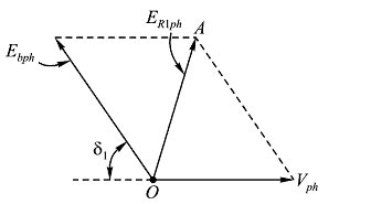
Ques.26. In a synchronous motor the rotor copper losses, are met by (SSC-2018 Set-4)
- Armature input
- D.C source
- Motor input
- Supply lines
Answer.2. D.C Source Explanation:- The synchronous motor consist of two parts: Stator: Stator is the armature winding. It consists of three-phase star or delta connected winding and excited by 3 phase A.C supply. Rotor: Rotor is a field winding. The field winding is excited by the separate D.C supply through the slip ring.
(i)The net mechanical output from the shaft
(ii) Copper losses in the armature winding
(iii) Friction and the armature core losses
Ques.27. The change of D.C. excitation of a synchronous motor changes (SSC-2018 Set-4)
- Motor Speed
- Applied voltage of the Motor
- Power Factor
- All Option is correct
Answer.3. Power Factor Explanation:- A synchronous motor is a machine that converts electric power into mechanical power at a constant speed called synchronous speed. It is a doubly excited machine because its rotor winding is excited by direct current and its stator winding is connected to an A.C supply. Stator: Stator is the stationary part of the machine. The three-phase armature winding is placed in the slots of the stator core and is wound for the same number of poles as the rotor. The stator is excited by a three-phase ac supply as shown in the Figure Rotor: The rotor of the synchronous motor can be of the salient pole or cylindrical pole (Non-salient) type construction. Practically most of the synchronous motor use salient i.e., projected pole type construction, except for exceedingly high-speed machines. The field winding is placed on the rotor and it is excited by a separate dc supply. Although the synchronous motor starts as an induction motor. it does not operate as one. After the armature winding has been used to accelerate the rotor to about 95% of the speed of the rotating magnetic field, direct current is connected to the rotor and the electromagnets lock in step with the rotating field. Notice that the synchronous motor does not depend on the induced voltage from the stator field to produce a magnetic field in the rotor. The magnet field of the rotor is produced by external DC applied to the rotor. This is the reason that the synchronous motor has the ability to operate at the speed of the rotating magnetic field. As the load is added to the motor, the magnetic field of the rotor remains locked with the rotating magnetic field and the rotor continues to run at the same speed. It should be noted that the changes in the dc field excitation do not affect the motor speed. However, such changes do alter the power factor of a synchronous motor. If all of the resistance of the rheostat is inserted in the field circuit, the field current drops below its normal value. A poor lagging power factor results. If the dc field is weak, the three-phase ac circuit to the stator supplies a magnetizing current to strengthen the field or the lagging reactive power will be drawn from A.C source to aid magnetization. This magnetizing component lags the voltage by 90 electrical degrees. The magnetizing current becomes a large part of the total current input. This gives rise to a low lagging power factor. If a weak dc field is strengthened, the three-phase ac circuit to the stator supplies less magnetizing current and the leading current is drawn from the ac source to compensate (oppose) the magnetization. Because this current component becomes a smaller part of the total current input to the stator winding, the power factor increases. The field strength can be increased until the power factor is unity or 100%. When the power factor reaches unity, the three-phase ac circuit supplies energy current only. The dc field circuit supplies all of the current required to magnetize the motor. The amount of dc field excitation required to obtain a unity power factor is called normal field excitation. The magnetic field of the rotor can be strengthened still more by increasing the dc field current above the normal excitation value. The power factor in this case decreases. The circuit feeding the stator winding delivers a demagnetizing component of current. This current opposes the rotor field and weakens it until it returns to the normal magnetic strength. Hence Higher PF means the low requirement of MMF for energy transfer, hence low magnetizing current requirement. The synchronous machine has separate DC excitation which reduces the machine’s excitation dependency on the main supply, hence better PF. whereas the Induction motor has no such provisions, hence low Power factor.
Ques.28. The advantage of a stationary armature of a synchronous machine is (SSC-2018 Set-4)
- Reducing the number of slip rings on the rotor
- The difficulty of providing high voltage insulation on the rotor
- The armature is associated with large power as compared to the field circuits
- All option are correct
Answer.4. All option are correct Explanation FIELD AND ARMATURE CONFIGURATIONS There are two arrangements of fields and armatures: In large alternators, rotating field arrangement is usually forward due to the following advantages. Hence in almost all of the alternators, the armature is housed in the stator while the dc field system is placed in the rotor.
ADVANTAGES OF ROTATING FIELD IN AN ALTERNATOR
Ques.29. In which of the following motors the stator and rotor fields rotate simultaneously (SSC-2018 Set-4)
- Reluctance motor
- Universal Motor
- D.C Motor
- Synchronous Motor
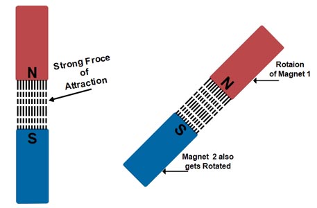
Answer.4. Synchronous Motor Explanation The synchronous motor is a truly constant speed motor. This is the specialty of this motor. Yet, it has very limited applications. To develop a steady torque, its rotor must be rotating at synchronous speed, Ns. This is the major defect of synchronous motors. Either it runs at synchronous speed, or it does not run at all.A The stator field rotates at synchronous speed due to the three-phase currents supplied to its windings. In order to develop a continuous unidirectional torque, it is necessary that the stator and rotor poles do not move with respect to each other. This is possible only if the rotor also rotates at the synchronous speed. Therefore Magnetic Locking between the poles is necessary to do so. The concept of Magnetic Locking For magnetic locking conditions, there must be two unlike poles and the magnetic axes of these two poles must be brought very nearer to each other. At zero speed or at any other speed lower than synchronous speed, the rotor poles rotate slower than the stator field. Therefore, in one cycle of rotation of the stator field, the N-pole of the rotor is for some time nearer to N pole of the stator and for some other time nearer to the S-pole of the stator. As a result, the torque developed is for some time clockwise and for some other time anticlockwise. Consequently, the average torque developed remains zero. Hence the Synchronous Motor Run either on Synchronous Speed Or Not at all.
![]()
Where f = supply frequency
P = Number of poles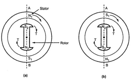
Ques.30. In a 3-phase synchronous motor, If the direction of its field current is reversed (SSC-2018 Set-4)
- The winding of the motor will burn
- The motor will stop
- The motor will run in the reverse direction
- The motor continues to run in the same direction
Answer.3. The motor continues to run in the same direction Explanation The synchronous motor is a doubly excited machine with a stator and Rotor. The stator is usually excited by the three-phase supply and the rotor is excited by a DC supply in order to create a magnetic field. The three-phase supply usually fed to the stator, the three-phase current is generated in the stator winding since it is a closed circuit. These current phases are separated by 120 degrees with each other. As a result, three-phase flux is generated which is equal in magnitude but are displaced by 120 degrees with each other. However, the rotor is excited by DC supply which usually creates poles of opposite polarity due to the positive and negative supply of dc. So the rotor is rotated by external means by using some pony Motors or induction motors so that it is interlocked with the stator field this rotates with the same speed as a stator named the synchronous speed. Interchanging the polarity during the running of the motor It should be noted that it is a very difficult procedure to change the polarity of the rotor suddenly. However, if we do so, the rotor will lose its magnetic interlocking with a stator for a second. Due to the inertia the rotor, it will be rotating with some speed. Now the stator speed is faster than the rotor, as a result, the rotor field is again interlocked with stator at a particular point of time during the run. Think of a magnet. It always looks for opposite polarity. So it will get interlocked at a particular point. Hence it rotates in the same direction as the stator. It neither changes its direction of rotation nor it stops All this happens in within seconds that it is impossible to trace because the normal operating speed is around 1500 rpm. At that speed, it is impossible to trace this effect. Hence the direction of rotation of the synchronous motor is determined by its starting direction, as initiated by induction motor action. Thus, to reverse the direction of a 3 phase synchronous motor, it is necessary to first stop the motor and then reverse the phase sequence of the 3 phase connections at the stator. REVERSING THE CURRENT TO FIELD WINDINGS WILL NOT AFFECT THE DIRECTION OF ROTATION