Ques.91. As the load is increased, the speed of a DC shunt motor will _________
Remain constant
Increase proportionately
Increase slightly
Reduce slightly✓
A large majority About 95 percent of the current drawn by the shunt motor flows in the armature circuit. Since the field current has little effect on the strength of the field, the motor speed is not affected appreciably by variations in load current. The relationship of the currents that flow through a DC shunt motor is as follows:
IT = IA + IF where:
IT = the total current drawn from the power source,
IA = the armature current
IF = the field current.
For a dc shunt motor field current is practically constant and thus the torque is directly proportional to the armature current. Hence the torque-armature current characteristic is a straight line passing through the origin. However, due to the armature reaction under the loaded conditions of the machine. the flux decreases slightly with the load. Since flux is practically constant for DC shunt motor. The speed of DC shunt motor is
N = K (V – IaRa)
The shunt-wound DC motor has very good speed regulation. The speed does decrease slightly when the load increases, as the result of the increase in
The voltage drop across the armature Increases as the load on the motor is increased. Thus, the speed of the dc shunt motor will fall slightly with the armature current. As the speed characteristic is only slightly drooping, the dc shunt motor is normally regarded as a constant speed motor.
Ques.92. Which one of the following generators are used for charging batteries?
Compound generator
Shunt generator✓
Series generator
Tacho generator
Battery charging requires a constant voltage supply of course DC. And the current required here is low as compared to the load current. So we could use a DC shunt generator for the use.
Shunt generators are used to charge batteries. In this application, the voltage should drop off slightly as the load increases, because the voltage of a lead battery is lower when the battery is discharged than when the battery is charged. Because of its drooping characteristic, the shunt generator is admirably suited for battery charging service. In a general way, the voltage curve of the generator has the same shape as the voltage curve of the battery itself. In both cases, as the load falls the voltage rises.
Ques.93. Fermi energy level for n-type extrinsic semiconductors lies ______
At the middle of the band gap
Close to the conduction band✓
Close to the valence band
None of these
Semiconductors can be classified into two types—intrinsic and extrinsic. Intrinsic semiconductors are pure elements like Si and Ge. At 0 K, the valence band is completely filled and the conduction band is empty. Semiconductors obtained by adding impurities (known as doping) to pure semiconductors are called extrinsic semiconductors.
Depending on the type of impurity used, semiconductors can be classified into n-type and p-type. If a group V (pentavalent) element like arsenic or phosphorous is added to the group IV element, four electrons of the group V element combine with those of the group IV element to form covalent bonds. The remaining one electron of the impurity atom is very weakly bonded with the parent atom and can easily be excited to the conduction band. This material in which, the conduction is due to these free electrons (called majority charge carriers) is called an n-type semiconductor.
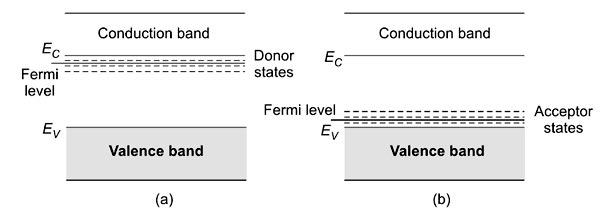
The impurity atom which donates free electrons to the crystal is called the donor. The donor energy levels lie below the conduction band edge [Fig.(a)]. If the doping is by group III element, all the three valence electrons enter into covalent bonding, leaving the vacancy of an electron to form saturated bonds. Thus, doping creates a hole. The material is called a p-type semiconductor with holes as the majority charge carriers. The impurity is called an acceptor impurity. Acceptor levels lie just above the valence band edge [Fig. (b)].
The Fermi level shifts upwards and lies close to the conduction band in n-type semiconductors. In p-type semiconductors, the Fermi level is closer to the valence band edge. These are also shown in Fig.
The valance band (VB) is usually completely filled with electrons at absolute zero. In contrast, the conduction band (CB) contains full unoccupied states at absolute zero.
As the name suggests it is the acceptor band ie it will accept the electrons. Since the electrons are present in the valence band. So, the acceptor band being closer to the valence band accepts electrons from it and creates holes.
Similarly, in n-type semiconductors, the donor band lies closer to the conduction band as it donates its electrons to the conduction band so that the flow of charge carriers can take place easily.
Ques.94. As compared to a split-phase motor, a capacitor start motor has ________.
Higher starting torque✓
Lower starting torque
Higher running torque
None of these
Capacitor-Start Motors
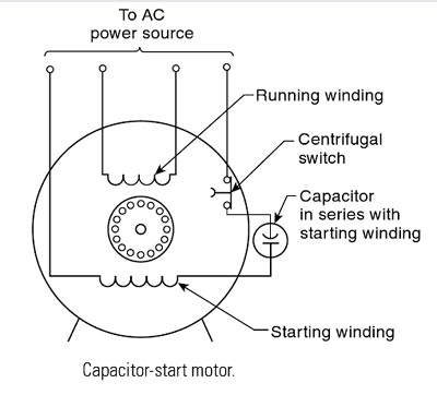
The capacitor start motor is identical to the split-phase motor in both construction and operation, except that a capacitor is installed in series with the starting winding, as shown in Fig.
Also, the starting winding of the capacitor start motor is usually wound with a larger wire than that used for the starting winding of the split-phase motor. The use of a capacitor in series with the starting winding causes the current in this winding to lead the voltage, whereas the current in the running winding lags the voltage by virtue of the high inductance of that winding. With this arrangement. the phase displacement between the two windings can be made to approach 90 electrical degrees so that the two-phase starting is achieved. For this reason, the starting torque of the capacitor start motor is very high, which makes it an ideal drive for the small compressor that must be started under full load.
Ques.95. Which law states that induced e.m.f. and current always opposes the cause producing them?
Lenz’s law✓
Fleming’s law
Faraday’s law
Maxwell’s law
Lenz’s law provides a way to determine the polarity of an induced emf. As per Faraday’s Law of electromagnetic induction, a current is induced in a conducting loop by the changing magnetic flux. This induced current itself produces a magnetic field and hence a magnetic flux. This magnetic flux may have the same sign as the original magnetic flux or may have the opposite sign. It strengthens the original magnetic flux if it has the same sign or weakens it if the opposite sign.
Lenz Law states that “ if there is changing magnetic flux through a loop, then an EMF is “induced” in the loop such that the resulting induced current opposes the change..” In other words, Every effect of induction acts in opposition to the cause that produces it. Here the effect is induced current and the cause is changing magnetic flux. That is, the induced current tends to keep the original magnetic flux through the loop from changing. We shall show that this law is a consequence of the law of conservation of energy.
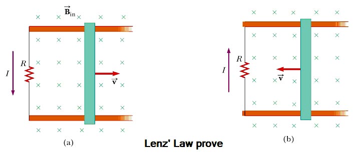
To understand Lenz’s law, consider the example of a bar moving to the right on two parallel rails in the presence of a uniform magnetic field (the external magnetic field, Fig. As the bar moves to the right, the magnetic flux through the area enclosed by the circuit increases with time because the area increases. Lenz’s law states that the induced current must be directed so that the magnetic field it produces opposes the change in the external magnetic flux. Because the magnetic flux due to an external field directed into the page is increasing, the induced current—if it is to oppose this change—must produce a field directed out of the page. Hence, the induced current must be directed counterclockwise when the bar moves to the right. (Use the right-hand rule to verify this direction.) If the bar is moving to the left as in Figure b, the external magnetic flux through the area enclosed by the loop decreases with time. Because the field is directed into the page, the direction of the induced current must be clockwise if it is to produce a field that also is directed into the page. In either case, the induced current attempts to maintain the original flux through the area enclosed by the closed-loop.
Let’s examine this situation using energy considerations. Suppose the bar is given a slight push to the right. In the preceding analysis, we found that this motion sets up a counterclockwise current in the loop. What happens if we assume the current is clockwise such that the direction of the magnetic force exerted on the bar is to the right? This force would accelerate the rod and increase its velocity, which in turn would cause the area enclosed by the loop to increase more rapidly. The result would be an increase in the induced current, which would cause an increase in the force, which would produce an increase in the current, and so on. In effect, the system would acquire energy with no input of energy. This behavior is clearly inconsistent with all experiences and violates the law of conservation of energy. Therefore, the current must be counterclockwise.
Hence Lenz’s Law ensures that, if the electrical energy gained is one unit then the mechanical energy lost is also one unit so that the net energy gain of the wire is zero. Energy is conserved.
Ques.96. Which type of earthing is also called as ‘fire earthing’?
I. Plate earthing II. Rod earthing III. Strip earthing
Only I
only II✓
Only III
I, II and III
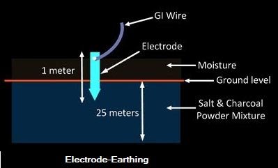
Rod earthing is also called as fire earthing.
Earthing rods
Earthing rods or ground electrodes are usually solid rods or pipes driven into the ground to make an earth connection, usually made of copper.A copper rod of 12.5mm (1/2 inch) diameter or 16mm (0.6in) diameter of galvanized steel or hollow section 25mm (1inch) of GI pipe of length above 1.5m (8.2 ft) are buried upright in the earth manually or with the help of a pneumatic hammer.It is the cheapest method of earthing and is employed in sandy areas.
Lightning rods intercept a discharge above a structure and direct the discharge to a safe path. In particular, lightning rods minimize the possibility of fire. A large plant site area needs a complete system of properly located lightning rods.
Ques.97. Gauge factor of the strain gauge is defined as the ratio of per unit change in the ____
Conductivity to the per unit change in applied force acting on the element
Resistance to the per unit change in the length of the element✓
Stress to the per unit change in strain of the element
Current to the per unit change in the length of the element
The strain gauge is a passive resistive transducer that is based on the principle of conversion of mechanical displacement into the resistance change.
The gauge factor is defined as the unit change in resistance per unit change in lengths. It is denoted as K or S. It is also called the sensitivity of the strain gauge.
S = (ΔR/R) ⁄ (ΔL/l)
Where
where
S = Gauge factor or sensitivity
R = Gauge wire resistance
ΔR – Change in wire resistance
I = Length of the gauge wire in the unstressed condition
Δl = Change in length in the stressed condition
Ques.98. A coil with large distributed capacitance has ______
High Q &low resonant frequency
High Q & High resonant frequency
Low Q &low resonant frequency
Low Q & high resonant frequency✓
Distributed capacitance: The amount of capacitance added to an inductor typically from the capacitance due to adjacent wires in a solenoid-type inductor. The distributed capacitance is given as a single capacitance figure for a specific inductor and can be defined as the equivalent capacitance across the entire coil. This would also allow the inductor to have a self-resonant frequency where the inductor resonates with the distributed capacitance with no external capacitance.
In addition to Q. the Q-meter can be used to measure inductance, the Q or dissipation factor of a capacitor, and the distributed capacitance, Cd, of an inductor.
If an inductor with capacitance Cd is placed in the Q-meter circuit, the total circuit capacitance includes both the Q-meters capacitance and the additional Cd. Therefore, when resonance is achieved, the actual resonating capacitance is more than what is indicated on the Q-meter capacitor’s dial. If Cd is not included in the calculation of inductance, the resulting value would be too large.
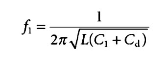
The relationship between the resonant frequency, fr, and the capacitor of the Q-meter to obtain resonance is
Where C1 is the capacitance set on Q-meter
If the value of C1 is constant then the resonant frequency
fr ∝ 1/Cd
So if the distribution Capacitance is large then the resonating frequency will decrease
Oscillation means that it is a ratio of resonant frequency to bandwidth and the higher the circuit Q, the smaller the bandwidth, Q = ƒr /BW.
Thus decrease capacitance will result in low resonant frequency also resulting in low Q value.T
Ques.99. Two resistors are connected in parallel to a stable voltage source. How do current and power of the resistor R1 change when the resistance of R2 is decreased by half?
Current is constant and power decreases
Current increases and power is constant
Both current and power constant✓
Both current and power decrease
Current across resistor R1
(IR1 )= V/R1
Power consumed by resistor R1
PR1 = V2 /R1
Since in the given case voltage across R1 is remains the same hence the current & power will also remain the same.
Ques.100. If an atom loses one or more electrons, it becomes ___________.
Electrically neutral
Electrically positive✓
Electrically negative
A neutral ion
Atoms are uncharged. The number of protons in an atom is the same as the number of electrons If an atom either gains or loses an electron, it will become electrically charged.
When an atom loses or gains electrons, it becomes electrically charged and is called an ion. An ion is an electrically charged atom formed by the loss or gain of one or more electrons.
If an atom gains one or more electrons, it becomes a negatively charged ion; an excess negative charge is present because of electrons outnumber protons.
If an atom loses one or more electrons, it becomes a positively charged ion; more protons are present than electrons. There is an excess positive charge.
Note that the excess positive charge associated with a positive ion is never caused by proton gain but always by electron loss. If the number of protons remains constant and the number of electrons decreases, the result is net positive charge. The number of protons, which determines the identity of an element, never changes during ion formation.
The charge on an ion depends on the number of electrons that are lost or gained. Loss of one, two, or three electrons gives ions with 1+. 2+, or 3+ charges, respectively. A gain of one, two, or three electrons gives ions with 1-, 2-, or 3- charges, respectively.
For SSC JE 2018 SET-1 Electrical paper with complete solutionClick Here
For SSC JE 2018 SET-2 Electrical paper with complete solutionClick Here
For SSC JE 2018 SET-3 Electrical paper with complete solutionClick Here
For SSC JE 2018 SET-4 Electrical paper with complete solutionClick Here
For SSC JE 2018 SET-5 Electrical paper with complete solutionClick Here
For SSC JE 2018 SET-6 Electrical paper with complete solutionClick Here
For SSC JE 2017 Electrical paper with complete solutionClick Here
For SSC JE 2015 Electrical paper with complete solutionClick Here
For SSC JE 2014 (Evening shift) Electrical paper with complete solutionClick Here
For SSC JE 2014 (Morning shift) Electrical paper with complete solution Click Here
For SSC JE 2013 Electrical paper with complete solutionClick Here
For SSC JE 2012 Electrical paper with complete solutionClick Here
For SSC JE 2011 Electrical paper with complete solution Click Here
For SSC JE 2010 Electrical paper with complete solution Click Here
For SSC JE 2009 Electrical paper with complete solution Click Here