Ques.21. A DC generator can be termed as
- Prime mover
- Power Pump
- Rotating Amplifier✓
- None of these
Cross-field machines are also called rotating amplifiers which are DC machines with an additional brush set. The output power is controlled by varying the field current of the generator. If P2 is the output power and P1 is the input power to the field winding, the power amplification becomes P2/P1. The input power is usually 1 percent of output power and hence P2/P1= 100. There is a power amplification in the DC generator. Since it is rotating, the rotating amplifier is Derived. Depending on the degree of compensation, the cross-Geld generators can be classified as (i) metadyne and (ii) amplidyne. Metadyne Metadyne is a two-stage generator combined in a single machine T It saves the cost of the additional machine used by the earlier two cases and the overall size is also reduced. It is a two-stage rotating amplifier. For this purpose, the armature has to generate two types of currents. One is required to provide the excitation to develop the necessary magnetomotive force for the second stage and second armature current to supply the power to the load or controlled machine. In cross-field machine two field fluxes are produced with an electrical or magnetic axis perpendicular to each other. To collect the electromotive forces generated by the two fluxes two sets of brushes are required. The other alternative is to use two opposite poles in the first stage and to use four poles for the second or the output stage. The word metadyne is used for cross-field machines. There are two versions of metadyne. In response to the constant input voltage, the metadyne convener can develop constant current output. Metadyne generator generally works with normal mechanical power. Amplidyne Amplidyne is somewhat similar to a metadyne generator. It is also a rotating amplifier. It amplified the input but it is not a stationary device like an electronic amplifier, a magnetic amplifier, or a transformer. It has two stages of generation. But the two stages of generation are not provided by two different machines. Similar to the metadyne generator, the two stages are combined in a single machine. Amplidyne is considered a fully compensated two-stage dc generator. Due to part compensation, the compensating winding of amplidyne is not in the form of a single coil used by metadyne.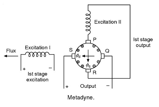
Ques.22. An e.m.f. is induced in the windings of an armature of a DC generator when the armature rotates in
- Alternating magnetic flux
- Magnetic field✓
- Electrostatic field
- Electromagnetic flux
Ques.23. Why is the air gap between the yoke and armature of an electric motor kept smaller?
- To achieve a stronger magnetic field✓
- To avoid overheating of the machine
- To make the station easier
- None of these
Ques.24. Which of the following devices can be used to test the windings of an inductor for continuity?
- Wattmeter
- Voltmeter
- Ohmmeter✓
- Wheatstone Bridge
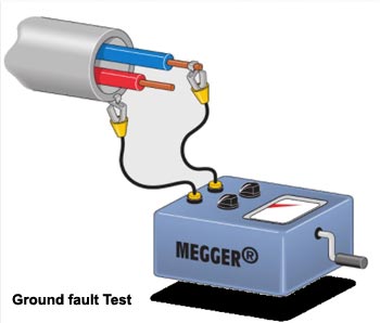
Insulation testing megger is a portable instrument used for testing the insulation resistance of a circuit, and for measuring the resistance of the order of megaohms in which the measured value of resistance is directly indicated on a scale. The megger can also be used to test continuity between any two points. When connected to the two points, if the pointer shows full deflection then there is electrical continuity between them. If there is a fault in the cable there will be no deflection the type of fault the megger can measure is given below. Open-circuit fault. When there is a break in the conductor of a cable, it is called an open-circuit fault. The open-circuit fault can be checked by a megger. For this purpose, the three conductors of the three-core cable at the far end are shorted and earthed. Then resistance between each conductor and earth is measured by a megger. The megger will indicate zero resistance in the circuit of the conductor that is not broken. However, if the conductor is broken, the megger will indicate infinite resistance in its circuit. Short-circuit fault. When two conductors of a multi-core cable come in electrical contact with each other due to insulation failure, it is called a short-circuit fault. Again, we can seek help or a megger to check this fault. For this purpose, the two terminals of the megger are connected to any two conductors. If the megger gives zero reading, it indicates a short circuit fault between these conductors. The same step is repeated for other conductors taking two at a time. Earth fault: When the conductor of a cable comes in contact with the earth, it is called earth fault or ground fault. To identify this fault, one terminal of the megger is connected to the conductor, and the other terminal is connected to the earth. If the megger indicates zero reading, it means the conductor is earthed. The same procedure is repeated for other conductors of the cable.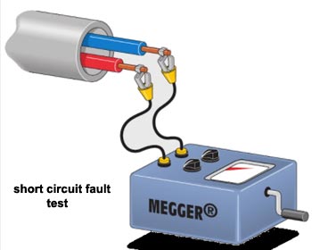
Ques.25. The series magnet of a single-phase Energy meter consists the coil of
- Thin wire of few turns
- Thick wire of few turns✓
- Thick wire of more turns
- Thin wire of more turns
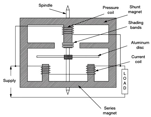
An induction-type instrument can be used as an ammeter, voltmeter, or wattmeter, the induction-type energy meters are more popular. Induction-type single-phase energy meter is used invariably to measure the energy consumed in an AC circuit in a prescribed period where supply voltage and frequency are constant. The energy meter is an integrating instrument that measures the total quantity of electrical energy supplied to the circuit in a given period. A single-phase energy meter has four essential parts: Operating System The operating system consists of two electromagnets. The cores of these electromagnets are made of silicon steel laminations. The coils of one of these electromagnets (series magnet) are connected in series with the load and are called the current coil. The Current coil consists of a few turns of thick wire, connected in series with the load. It carries full load current which depends upon the angle of lag or lead of the load. Therefore the currents in the pressure coil and current coil have a phase difference of nearly 90 degrees. The other electromagnet (shunt magnet) is wound with a coil that is connected across the supply, called the pressure coil. The voltage coil consists of many turns of fine wire encased in plastic, connected in parallel with the load, and is highly inductive. This coil is connected in parallel with the supply or load and carries current proportional to voltage. The current in this coil lags behind the voltage approximately by 90 degrees. The pressure coil, thus, carries a current that is proportional to supply voltage. Shading bands made of copper are provided on the central limb of the shunt magnet. Shading band as will be described later, are used to bring the flux produced by a shunt magnet exactly in quadrature with the applied voltage. The two field fluxes produced by the pressure coil and current coil act on the aluminum disc, induce eddy currents in the disc, and hence the disc rotates due to the interaction of the two fluxes developed. The speed of the disc is proportional to the product of voltage, current, and the number of revolutions of the disc (i.e. time). In other words, the disc speed is proportional to the energy consumed by the load. The number of revolutions completed by the disc for one kilowatts hour is called meter constant.Induction-type Single-phase Energy Meter
Ques.26. The leakage current must not be more than ____________ of maximum supply current
- 1/1000
- 1/100
- 1/5000✓
- 1/150
Leakage current is an unwanted conductive path other than short circuit i.e under normal operating conditions. Ideally, the current leaking from the power supply unit should flow through the ground connection and into the installation’s earth ground. As per the Indian electricity rules, the leakage current of an installation should not exceed 1/5000 of the maximum supply-demand of the consumer.
Ques.27. The function of the measurement system is/are
- Indicating function
- Recording function
- Controlling function
- Indicating, recording and controlling function✓
Measurement of electrical quantities such as current, voltage, power, and energy are made using instruments called measuring instruments. Such instruments are in use in laboratories, industries, and control stations. Classification of Measuring instruments Measuring instruments can be classified into separate categories based on different criteria. These classifications are useful in knowing the characteristics of instruments and their selection for a particular use. Instruments are classified as active and passive instruments, primary or absolute instruments, secondary or derived instruments, null type, and deflection type instruments, indicating instruments, integrating instruments, recording instruments, analog and digital instruments, monitoring and control instruments, electromechanical and electronic instruments, etc. Indicating, Recording, and Controlling Function Indicating Function:- Indicating instruments give the output as a function of time through the movement of a pointer over a graduated scale These are, therefore, called analog instruments The deflection type ammeters, voltmeters, and wattmeters in your laboratory are indicating instruments. Voltmeters, ammeters, wattmeters, PMMC, etc. are of indicating type which is extensively used in laboratories and control panels. Recording Function:- Recording instruments create a written record usually on paper of the time-varying quantity. The measurement system carries a pen which is used to record the value of the time-varying quantity on a paper which is driven by a slow-moving motor drive. The curve traced on the paper indicates the actual variation in the value of the quantity being measured. For example, the temperature can be measured and recorded continuously using a recording-type instrument. An ECG machine, the status of the health of your heart is recorded on a slow-moving paper and can be classified as a recording type instrument. For satisfactory operation of any analog instrument the following systems or functions must be present in the instrument: Deflecting System: In order to move the pointer from its zero position on the scale deflecting torque is required. The deflecting torque works on the moving system to which the pointer is attached. Controlling system.: The controlling force is equal and opposite to the deflecting torque in order to make the deflection of the pointer proportional to the magnitude of the quantity to be measured. The controlling force also brings the pointer back to zero position when the force which causes the movement of the pointer is removed. Damping system: Before coming to the rest, the pointer oscillates about the equilibrium position. The damping system provides the damping torque so that the pointer quickly comes to the final steady-state position without any swing or oscillations
Ques.28. If voltage Standing Wave Ratio, (VSWR) of a wave is 2, its reflection coefficient will be
- 0
- 1/2
- 1/3✓
- 1/4
The ratio of maximum voltage to the minimum voltage on a line is called the Voltage Standing Wave Ratio (VSWR). Therefore: VSWR = Vmax/Vmin = (1 + Γ)/(1 − Γ) ————1 Where Γ = Reflection coefficient = (VSWR − 1) ⁄ (VSWR + 1)———-2 Given VSWR = 2 Γ = (2 − 1)/(2 + 1) = 1/3
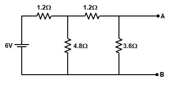
Ques.29. The resistance across terminals ‘a’ and ‘b’ in the circuit shown will be __________.
- 10.8 Ω
- 2.45Ω
- 6 Ω
- 1.35 Ω✓
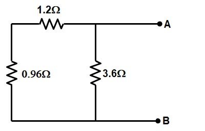
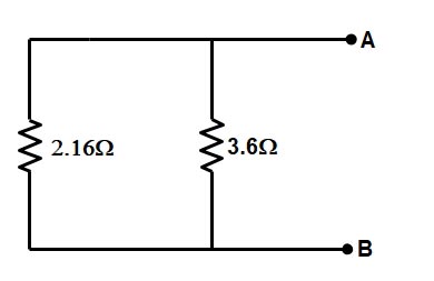
Applying Thevenin’s theorem in the given question Thevenin’s resistance can be found by replacing 6 V source with a short-circuit. To find the Thevenin’s resistance first we have to reduce the circuit. ⇒The resistance 1.2 Ω and 4.8 Ω are in parallel = (1.2 × 4.8) ⁄ (1.2 + 4.8) = 0.96Ω ⇒ Now the Resistance 0.96 Ω and 1.2 Ω are in series = 0.96 + 1.2 = 2.16Ω ⇒ Finally, the Resistance 2.16 Ω and 3.6 Ω are in parallel = (2.16 × 3.6) ⁄ (2.16 + 3.6) = 1.35Ω Rab = 1.35Ω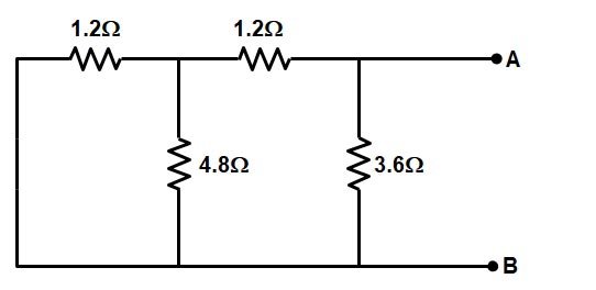
Ques.30. The electric flux and field intensity inside a conducting sphere is
- Maximum
- Uniform
- Zero✓
- Minimum
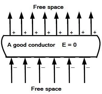
When the magnitude of the induced field becomes equal to that of the applied field, the net field intensity inside the conductor will become zero That is the Electric field due to the charges inside the conductor is directed opposite to the electric field outside due to which the field inside the conductor originated. Remember: The charges move in a conductor so as to kill the external field Consequently, no further movement of charges will take place. That is, the static condition will be reached after a brief transient period during which charges move to the surfaces. External field lines terminate on the bottom surface and emerge from the top surface, as shown in the figure. Since field intensity inside a good conductor is zero, the potential gradient, which is numerically equal to the field intensity, is also zero. Accordingly, the potential has the same value everywhere inside a good conductor.Why is the electric field inside a conductor zero?