Ques.31. The generator of a power station produces an electric pressure by ________
- Conversion of heat
- Magnetic induction
- Conversion of light
- Mechanical pressure✓
In generating a power station the mechanical energy is converted into electrical energy. For e.g In the thermal power plant, the steam generator and alternator are the most important equipment for power generation. The coal-handling plant supplies coal to the boiler. The coal is burnt in the boiler and generates the heat that is used to convert water into steam at the required pressure and temperature, which is attained by further heating the steam in the superheater. The steam is then fed to the high-pressure turbine. The expansion of steam in the turbine produces the mechanical power at the shaft to which the alternator is coupled. The mechanical energy input to the alternator is finally converted into electrical power.
Ques.32. The speed of a DC shunt motor is required to be more than F.L(Full Load) speed. This is possible by ___________.
- Increasing the armature current
- Decreasing the armature current
- Increasing the excitation current
- Reducing the field current✓
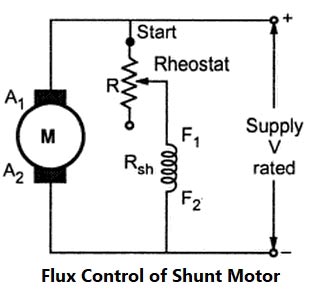
The speed of the DC shunt can be controlled by various Methods such as The speed of DC Shunt Motor is inversely proportional to the flux. The flux is dependent on the current through the shunt field winding. Thus flux can be controlled by adding a rheostat (variable resistance) in series with the shunt field winding. At Starting the rheostat R is kept at the minimum. The supply voltage is at its rated value. So the current through shunt field winding is also at its rated value. Hence the speed is also rated speed i.e at normal speed. When the resistance R is increased due to which shunt field current Ish decreases, hence decreasing the flux produced. As N =(I/Φ), the speed of the motor increases beyond its rated value. Now as we know that the speed of DC motor is directly proportional to the flux hence when the speed is increased the back EMF also increased. Thus by this method, the speed control above the rated value is possible.
Flux Control Method
Ques.33. The rotating part of a DC motor is known as ______
- Pole
- Stator
- Armature✓
- Carbon Brush
Armature The armature is the rotating part of the dc machine. The armature of the dc machine consists of a shaft upon which a laminated cylindrical core is mounted called armature core. The armature core has slots on its outer surface. The laminations are insulated from each other and tightly clamped together. The purposes of using these laminations are to minimize the eddy circuit loss. The armature is one of the very important requirements of DC machines without which the whole operation results in failure. Basically, two types of windings are used in DC machines, they are lap and wave winding. Field system The magnetic field system is a stationary part of the d.c. machine. The main purpose of the field system is to produce a uniform magnetic field in the air gap, within which the armature rotates. Electromagnets are preferred in comparison with permanent magnets due to their greater magnetic effect. The outer frame or yoke is a hollow cylinder of cast steel. Even number of poles are bolted to the yoke. The yoke is one of the essential parts of DC machine. It is necessary due to the following reason: (a) It provides a path for the magnetic circuit As the poles project inwards they are called salient poles. Each pole core has a pole shoe having a curved surface. The pole shoe performs the following two requirements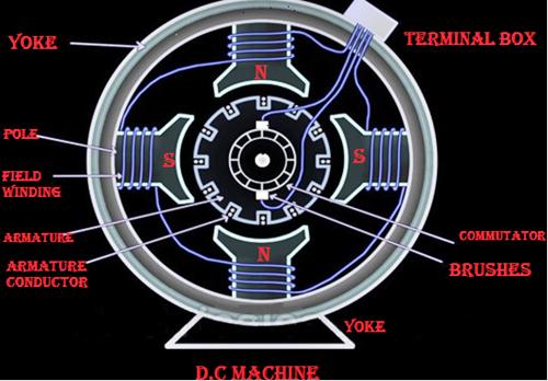
(b) It supports the pole core and acts as protective shielding to the machine.
(a) It sups ports the field coils
(b ) It reduces the reluctance by increasing the cross-sectional area of the magnetic circuit.
Ques.34. What happens to current flow in a capacitance circuit when the DC voltage across the capacitor is approximately equal to the source voltage?
- Current flow is optimized
- Little current flows✓
- Current flow is maximum at the source
- Current flow is maximum at the capacitor
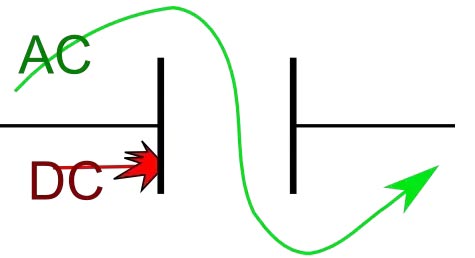
Just like resistors, capacitors also offer some form of resistance against the flow of current through the circuit, but with capacitors, in AC circuits this AC resistance is known as Reactance. Capacitive Reactance = 1/2πfC As the frequency is increasing the capacitive reactance is slowly reaching zero value. In AC circuit we suppose that the frequency value is sufficiently high to make capacitive reactance zero or the capacitor behaves equivalent to the short circuit.
Ques.35. In the dynamometer type of wattmeter, which of the coil is split up into two parts?
- Pressure coil
- Current Coil✓
- Both the pressure coil and current coil
- None of these
An indicating instrument used to measure power in an electric circuit is called wattmeter. Principle The basic principle of dynamometer-type instruments is that when a current-carrying moving coil is placed in the magnetic field produced by the current-carrying fixed coil, a force is exerted on the coil sides of the moving coil and deflection takes place. In other words, when the field produced by the current-carrying moving coil tries to come in line with the field produced by the current-carrying fixed coil a deflecting torque is exerted on the moving system and deflection takes place. Construction The various parts of the electrodynamometer type instrument are Fixed Coils: The dynamometer-type wattmeter essentially consists of two coils called fixed coil and moving coil. The fixed coil is split into two equal parts that are placed parallel to each other, as shown in Figure. The two fixed coils are air-cored to avoid hysteresis effects when used on AC. The fixed coil is connected in series with the load and carries the circuit current. It is, therefore, called the current coil. The coils are usually varnished. They are clamped in place against the coil supports. This makes the construction rigid. Moving Coil: The moving coil is pivoted between the two parts of the fixed coil and is mounted on the spindle. The moving coil is connected in parallel with the load and carries the current proportional to the voltage applied across the load. It is, therefore, called a potential coil. Generally, a high resistance is connected in series with the moving coil to limit the current through it. By limiting the current, the moving coil is made thin and light in weight which in turn increases the sensitivity of the instrument. The construction of the moving coil is made light as well as rigid. It is air-cored. Controlling: The controlling torque is provided by springs. These springs act as leads to the moving coil.
Ques.36. Branch circuit must not feed more than __________ points
- 5
- 10✓
- 12
- 8
The branch Circuit must not feed more than 10 points.
Ques.37. In an energy-meter which coil carries the current proportional to supply voltage
- Current Coil
- Pressure coil✓
- Both pressure and current coil
- None of these
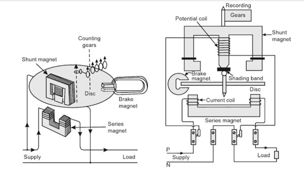
An induction-type instrument can be used as an ammeter, voltmeter, or wattmeter, the induction-type energy meters are more popular. Induction-type single-phase energy meter is used invariably to measure the energy consumed in an AC circuit in a prescribed period where supply voltage and frequency are constant. The energy meter is an integrating instrument that measures the total quantity of electrical energy supplied to the circuit in a given period. Principle The basic principle of an induction-type energy meter is electromagnetic induction. When AC flows through two suitably located coils (current coil and potential coil), they produce the rotating magnetic field that is cut by the metallic disc suspended between the coils, and thus, an emf is induced in the disc that circulates eddy currents in it. By the interaction of rotating magnetic field and eddy currents, electromagnetic torque is developed that causes the disc to rotate. This is the same principle that is applied in single-phase induction motors. A single-phase energy meter has four essential parts: Operating System The operating system consists of two electromagnets. The cores of these electromagnets are made of silicon steel laminations. The coils of one of these electromagnets (series magnet) are connected in series with the load and are called the current coil. The other electromagnet (shunt magnet) is wound with a coil that is connected across the supply, called the pressure coil. The pressure coil, thus, carries a current that is proportional to supply voltage. Shading bands made of copper are provided on the central limb of the shunt magnet. Shading bands, as will be described later, are used to bring the flux produced by a shunt magnet exactly in quadrature with the applied voltage. Moving System The moving system consists of a light aluminum disc mounted on a spindle. The disc is placed in the space between the series and shunt magnets. The disc is so positioned that it intersects the flux produced by both the magnets. The deflecting torque on the disc is produced by an interaction between these fluxes and the eddy current they induce in the disc. In energy meters, there is no control spring as such, so there is the continuous rotation of the disc. Braking System The braking system consists of a braking device which is usually a permanent magnet positioned near the edge of the aluminum disc. The arrangement is shown in Figure. The emf induced in the aluminum disc due to relative motion between the rotating disc and the fixed permanent magnet (brake magnet) induces an eddy current in the disc. When the disc rotates in the air gap, eddy currents are induced in the disc which opposes the cause producing them i.e. relative motion of the disc with respect to the magnet. This eddy current, while interacting with the brake magnet flux, produces a retarding or braking torque. This braking torque is proportional to the speed of the rotating disc. When the braking torque becomes equal to the operating torque, the disc rotates at a steady speed.Induction-type Single-phase Energy Meter
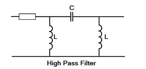
Ques.38. The shunt element of prototype high filter is
- Resistive
- Inductive✓
- Capacitive
- Combination of inductance and capacitance
A filter is a circuit that is designed to pass a specified band of frequencies while attenuating all the signals outside that band. It is a frequency selective circuit. Low Pass Filter:- The low pass filter passes the low-frequency signal from input to output while it blocks high-frequency signals from the input. A low pass filter (even or odd orders based on a ladder network consists of shunt capacitors and series inductors that interconnect these shunt capacitors. No inductor is grounded. The load impedance/resistance is always grounded. For an even order low pass filter, the least reactive element is always an inductor, whereas, for an odd order filter, the least reactive element is always a capacitor. High Pass Filter:- In a high pass filter, the filter rejects the frequencies which are less than cut-off frequencies ωo and it allows to pass the frequencies which are greater than ωo. The topology of a ladder network-based high pass filter is complementary to that of a ladder network-based low pass filter. Now all inductors are shunted, and series capacitors interconnect these shunt inductors. The load impedance/resistance is always grounded. Band Pass Filter:- A band-pass filter is one designed to pass signals with frequencies between two specified cut-off frequencies. A ladder network-based bandpass filter consists of alternating pairs of series and parallels connected capacitors and inductors. Each pair of parallel-connected capacitors and inductors is grounded. Each series-connected pair of capacitor and inductor interconnects two pairs of parallel-connected capacitor and inductor.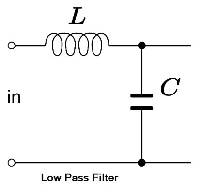
Ques.39. Static electricity is produced by
- Chemical Reaction
- Friction✓
- Induction
- Both friction and Induction
Static Electricity The oldest method of moving electrons is by static electricity. Static electricity produces a flow of electrons by permanently displacing an electron from an atom. The main characteristic of static electricity is that a prolonged or steady flow of current is not possible. As soon as the charges between the two substances are equalized (balanced, electron flow stops. Static electricity is an electric charge that does not flow in an electric current from a battery or along an electric wire to light a bulb or some other electric tool. Static electricity is a charge that stays in one place. Static electricity can be produced by friction when two materials are rubbed together. During the process of rubbing, electrons can be rubbed off from the atoms of one material and onto the atoms of another material. The materials used to create a static charge must be electrical insulators, materials that do not conduct electricity. If they were conductors, like copper, aluminum, or water, the charge would just flow away. Some common insulators that create static charges are rubber, cloth, hair, and plastic. Electricity Through Chemical Means Electricity can also be produced by the movement of electrons due to chemical means. A battery produces an electron flow by a chemical reaction that causes a transfer of electrons between two electrodes. An electrode is a solid conductor through which an electric current can pass. One electrode collects electrons and one gives away electrons. The dry cell battery uses two electrodes made of two dissimilar metals inserted in a pastelike electrolyte. Electricity is produced when a chemical reaction occurs in the electrolyte between the electrodes, causing an electron flow. Electricity Through Magnetism or Induction The magnetic or induction method of producing electron flow uses a conductor to cut through a magnetic field, which causes a displacement of electrons. The alternator, generator, and transformer are the best examples of the magnetic method. The magnetic method is used to supply electricity to consumers. The flow of electrons in a circuit produces magnetism, which is used to cause movement, or thermal energy, which in turn is used to cause heat. A magnetic field is created around a conductor—an apparatus for electrons to flow through—when there is a flow of electrons in the conductor. The flow of electrons through a conductor with resistance will cause heat, such as in an electric heater. The heating, cooling, and refrigeration industry uses magnetism to close relays and valves and to operate motors by using coils of wire to increase the strength of the magnetic field.
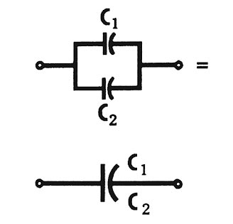
Ques.40. How will the total capacitance change, when two capacitors are connected in parallel?
- The total capacitance increases✓
- The total capacitance decreases
- The mean value gives the new capacitance
- The total capacitance is found by the reciprocal equation
Capacitance in Parallel When two equal capacitors are connected in parallel, the plates of the individual capacitors, in effect, combine to form one capacitor representing total capacitance. Notice in Figure. that the effective plate area of the equivalent capacitor has doubled. Since an increase in plate area increases capacitance, it can be concluded that the total capacitance of the two capacitors in parallel is equal to the sum of the two capacitors. This direct relationship between total capacitance and capacitors in parallel is described bit this equation: CTotal = C1 + C2 Mathematically, The charge on a capacitor is given as Q = CV Where C is the capacitance V is the applied voltage In the parallel circuit, the voltage remains the same and the charge depends upon the capacitor size. Q1 = C1V Q2 = C2V Q = Q1 + Q2 CeqV = C1V + C2V Ceq = C1 + C2 Hence in the parallel plate capacitor, the capacitance increases.