
Ques.41. For which of the following DC motors, is the typical field of application mentioned?
- Shunt motor: Electric trains
- Series motor: Machine tools
- Series motor: Belt drive
- Compound motor: Flywheel drive✓
Direct current compound motors are used in applications where relatively constant speed under varying loads and large starting torques are required but where the led may fall to such a small value that a series motor would reach a dangerously high speed. Where the supply voltage may fluctuate, for instance on a traction system, the series winding reduces the fluctuation of armature current, partly by its inductance and partly by its influence on the value of the flux and therefore on that of the induced emf. They are frequently used on machines that require re sudden application of heavy loads, such as presses, shears, compressors, reciprocating tools, and elevators. Compound motors are also used when it is desired to protect the motor by causing it to decrease in speed under heavy loads. When the load is of a fluctuating nature, e.g. for driving stamping processes, etc. the shunt excitation prevents the speed from becoming excessive on light load, and the decrease of speed with an increase of load enables the flywheel, usually fitted to such a machine, to assist the motor in dealing with the peak load by giving up some of its kinetic energy. Flywheel Effect The power required by some machine tools is very irregular. For example, in a punch press or stamping machine, almost no power is required until the punch or die comes in contact with the material. If the moving parts in such a machine are not very heavy the current taken by the driving motor will vary widely. The figure shows this current curve. The motor selected to drive such a machine must be capable of carrying the greatest value of current without overheating or excessive arcing at the brushes. If a considerably over-compounded motor is used (about 30%) with a heavy flywheel, the armature current will vary less, as indicated by the dotted curve in Figure. From this curve, it can be observed that the driving motor may be much smaller when a flywheel is used. The effect of the flywheel can be explained as follows. At the point “a” as shown in Figure, the load on the motor and flywheel suddenly increases, causing them to slow down. The centrifugal force of the flywheel supplies the energy to help overcome the opposition of the load. This reduces the demand on the motor. In other words, with an increase in load, the flywheel assists the motor in driving the load. Although the motor current increases, it does not increase as much as it would without the flywheel. At point b, the power required to drive the load is less than the input to the motor. As a result, there is an increase in rotor speed. The increased speed produces a greater counter emf, causing a decrease in current. This process continues as long as the machine is in operation.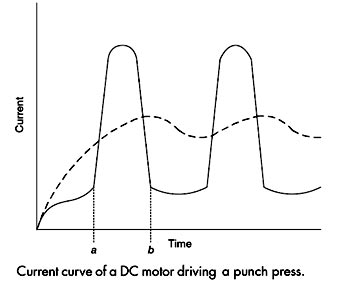
Ques.42. A simple method of increasing the voltage of a DC generator is
- To decrease the air gap flux density
- To increase the speed of rotation✓
- To decrease the speed of rotation
- To increase the length of the armature
The voltage generated by the DC generator is given as Eg = PφZN/60A where P – Number of poles of the machine ϕ – Flux per pole in Weber. Z – Total number of armature conductors. N – Speed of armature in revolution per minute (r.p.m). A – Number of parallel paths in the armature winding. Hence from the above relation, the voltage generated is directly proportional to the speed of the rotation flux per pole, number of armature conductors, Number of poles Eg ∝ N Hence Generated voltage can be increased by increasing the speed of rotation.
Ques.43. What is the effect produced by the electric current in an electric motor?
- Magnetic effect only
- Magnetic as well as the heating effect✓
- Heating effect only
- Heating as well as the chemical effect
Any movement of electricity, or flow of CURRENT, through any conductor causes two things to happen: Heating Effect:- On flowing of electric current in any conductor carrying resistance, free electrons colliding with the atoms of conductor and in this collision the main portion of the kinetic energy of electrons are transferred to the atoms by which the internal kinetic energy of the conductor increases, so its temperature increases. This change of electrical energy into heat energy is called the heating effect of electric current. Magnetic Effect:- The term “magnetic effects of current”mean that ” a current flowing in a wire produces a magnetic field around it”. The magnetic effect of current was discovered by Oersted found that a wire-carrying current was able to deflect a magnetic needle. It concludes that a current flowing in a wire always gives rise to a magnetic field around it, the electric motor, telephone, and radio, all utilize the magnetic effect of current. An electric motor also uses the effect of flowing current to produce a magnetic field. In a motor, the magnetic field that is produced by electricity interacts with another magnetic field to produce torque. Usually, in small motors, the wire is coiled around an assembly located in the center of the motor called a rotor or armature. The outside assembly of the motor is stationary and lined with permanent magnets and called a stator. As current flows through the wire wound around the rotor, the magnetic field that is produced interacts with the magnetic field of the stator and the torque causes the rotation to result. As the wire assembly rotates, an electrical connection is made through a conductive ring and brush.
This effect is utilized in the instruments producing heat and light viz electric bulb heater, electric iron, electric arc etc. In these instruments, the electric energy changes into heat energy. This effect is also responsible for wasteful energy losses, due to heat transfer away from a conductor into its surroundings.
Ques.44. In a standard multimeter for measuring AC voltage, parameter of __________ voltage is measured.
- Peak-to-peak
- Peak
- Average value
- RMS✓
The root mean square (RMS) or effective value of an AC voltage, current or power waveform is the DC vale equivalent of the AC wave. For example, say you want to find out the direct current value that will have the same heating effect on a resistor as the AC current that you have. Then you calculate the RMS value of the AC current. This gives you the DC value that will have the same effect as the AC current. In this case, it is the DC current that will heat the resistor up to the same temperature as the AC current at the same time and under the same conditions. A multimeter, also known as a VOM (Volt-Ohm-Milliammeter) is a combination of a voltmeter, ohmmeter, and a current meter. it is an indicating electronic instrument that can be used for the measurement of three quantities, namely voltage, current, and resistance. This instrument can also be used for both dc and ac voltages and currents thus the reading on the meter is an “RMS” or “root mean square” reading. Multimeters are available in both analog and digital forms. Although analog multimeters are being replaced by digital multimeters.
Ques.45. The current transformer that is used to measure a 100 A current by 5 A ammeter is a ________.
- Step-up transformer✓
- Step down transformer
- Power transformer
- Distribution transformer
Instrument transformers are used in conjunction with an ammeter and voltmeter to extend the range of meters. In dc circuit shunt and multipliers are used to extend the range of measuring instruments. The shunt is used to extend the range of the ammeter whereas the multiplier is used to extend the range of voltmeters This type of ammeter is shown in Figure. The primary of the transformer is connected in series with the load, and the ammeter is connected to the secondary of the transformer. Notice that the range of the meter is changed by selecting different taps on the secondary of the current transformer. The different taps on the transformer provide different turn-ratios between the primary and secondary of the transformer. The working is explained in detail.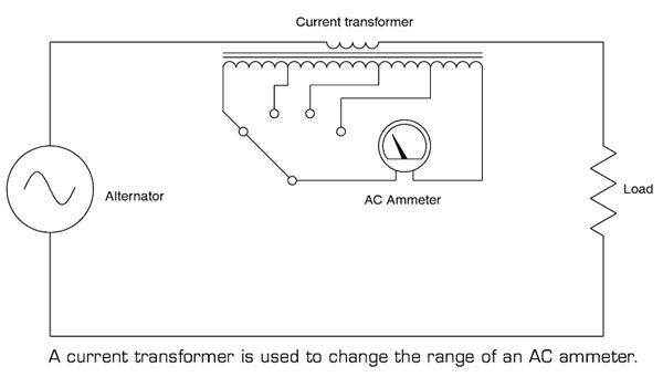
Ques.46. Which set of rules is to be verified on the completion of wiring on any new installation?
- Indian Electricity rules, 1950
- Indian Electricity rules, 1956✓
- Indian Electricity rules, 1960
- None of these
The Indian Electricity Rules, 1956 was made under section 37 of the Indian Electricity Act, 1910 (now repealed after enactment of The Electricity Act, 2003, but these rules themselves have been allowed to be in force till rules under section 53 of the new Act are made). These Rules mainly deal with:- i. Appointment of inspectors & their duties.
ii. Licensing provisions.
iii. General safety requirements.
iv. Conditions relating to supply and use of energy.
v. Electric supply lines and systems for LV & MV.
vi. Electric supply lines and systems for HV & EHV.
vii. Overhead lines, underground cables, and generating stations.
viii. Electric traction.
ix. Precautions in mines & oil fields.
Ques.47. In a flux meter, the controlling torque is
- Produced by weights attached to the moving coil
- Produced by spring
- Not provided at all✓
- Provided by crossed coil mechanism
A special ballistic galvanometer with very small controlling torque and high electromagnetic damping is used as a flux meter. It consists; of a small cross-section carrying a coil. The cross-section is suspended in the narrow air gap of the permanent magnet. The cross-section is suspended win the help of spring support and a single thread of silk. The current is injected to the coil through very thin, annealed silver springs as shown in the figure. The pointer is fitted to the moving system of the fluxmeter and the scale is calibrated in terms of flux turns. Such a flux meter is designed by Grassot and hence it is called Grassot flux mete. The spirals of silver springs keep the controlling torque to a minimum. As controlling torque is minimum, the pointer takes time to come back to the zero position. But readings may be taken by observing the difference in deflection at the beginning and end of the change in flux, without waiting for the pointer to restore its zero position. The fluxmeter is the advanced form of the ballistic galvanometer which has certain advantages like the meter has negligible controlling torque and heavy electromagnetic damping.
Ques.48. For a prototype high pass filter, the series element is
- Resistive
- Inductive
- Capacitive✓
- Combination of inductance and capacitance
A filter is a circuit that is designed to pass a specified band of frequencies while attenuating all the signals outside that band. It is a frequency selective circuit. Low Pass Filter:- The low pass filter passes the low-frequency signal from input to output while it blocks high-frequency signals from the input. A low pass filter (even or odd orders based on a ladder network consists of shunt capacitors and series inductors that interconnect these shunt capacitors. No inductor is grounded. The load impedance/resistance is always grounded. For an even order low pass filter, the least reactive element is always an inductor, whereas, for an odd order filter, the least reactive element is always a capacitor. High Pass Filter:- In a high pass filter, the filter rejects the frequencies which are less than cut-off frequencies ωo and it allows to pass the frequencies which are greater than ωo. The topology of a ladder network-based high pass filter is complementary to that of a ladder network-based low pass filter. Now all inductors are shunted, and series capacitors interconnect these shunt inductors. The load impedance/resistance is always grounded. Band Pass Filter:- A band-pass filter is one designed to pass signals with frequencies between two specified cut-off frequencies. A ladder network-based bandpass filter consists of alternating pairs of series and parallels connected capacitors and inductors. Each pair of parallel-connected capacitors and inductors is grounded. Each series-connected pair of capacitor and inductor interconnects two pairs of parallel-connected capacitor and inductor.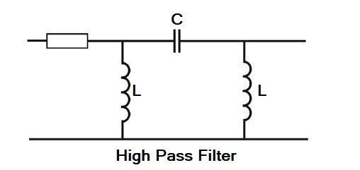
Ques.49. Which of the following is an active element of a circuit?
- Resistance
- Inductance
- Capacitance
- Ideal current source✓
The active elements generate energy or which gives power to the circuit elements. Like voltage source and the current source, Batteries, generators, operational amplifiers, etc are active elements.
Ques.50. Two condensers of capacity 2F and 3F are connected in series, the third condenser of 1F is connected in parallel to them, the resultant capacity in Farad (F) will be
- 6F
- 5/11 F
- 5/6 F
- 11/5 F✓
Capacitor 2F and 3F are connected in series, therefore, the resultant capacitance C = (2 × 3)/(2 + 3) = 1.2 F Now Capacitor 1.2 F and 1 F are connected in parallel hence C = 1.2 F + 1F = 2.2 F = 11/5 F