
Ques.61. Which of the following is a correct statement about a series motor?
- Its field winding consists of thicker wire and less turns✓
- It can run easily without load
- It has an almost constant speed
- It has poor torque
In a dc series, motor and generator respectively as the field winding is connected in series with the armature, If= Ia = IL. In the case of a dc series machine, therefore, the field winding is made up of thick winding wires such that the armature current can flow through wires of the field winding without overheating. Also since the series winding carries the whole of load current, it is designed to have very low resistance (about 0.5Ω). For this reason, series field winding has a few turns of thick wire.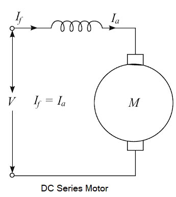
Ques.62. In a DC motor, where does iron loss occur?
- Yoke
- Armature✓
- Field
- None of these
In the rotating machine whether it is AC or DC machine the type of losses are almost the same The various losses in a d.c. the machine, whether it is a motor or a generator, is categorized amplified into three groups as: Copper losses are also called Electrical losses, winding losses, or Ohmic losses. The copper losses are the losses taking place due to the current flowing in a winding. There are basically two windings in a d.c. machine namely armature winding and field winding. The copper losses are proportional to the square of the current flowing Through these winding; Thus the various copper losses can be given by Core losses are also known as iron losses or Magnetic losses. These Losses are constant and independent of the load. They are induced in the machine due to hysteresis and eddy currents produced in the core produced when the magnetization is changing. They mainly occur in the armature teeth and core as also in the pole shoe. Hysteresis losses occur due to the reversal of the magnetization of the armature core. So, the hysteresis loss can be obtained as: Hysteresis Loss = Kh × BM1.67 × f × v watts where The eddy current loss exists due to eddy currents. When the armature core rotates, it cuts the magnetic flux and e.m.f. gets induced in the core. This induced e.m.f. sets up eddy currents which cause power loss. Eddy current losses = Ke × Bm2 × f2 × t2 Where Ke = Eddy current constant These losses are produced due to friction and windage (friction with air) caused by machine rotation. Hence, these are named mechanical losses. Some power is required to overcome mechanical friction and wind resistance at the shaft. They depend on the speed of the machine. The mechanical losses are also constant for a d.c. machine Bearing friction loss generally depends on the type of bearing used and on the viscosity of the lubricant. Brush friction loss is proportional to the contact area and the brush pressure. It also depends on other factors like the material of the brush and commutator, their polish condition, and the temperature at the contact surface. The magnetic and mechanical losses together are called stray losses. Stray load losses are losses that are produced in the machine when they are loaded. They cannot be considered with the main losses listed above. These losses include: (a) Additional core loss resulting from armature reaction distortion. (b) Copper loss due to short circuits produced in coils, segments, and brushes during commutation. (c) Copper loss due to non-uniform distribution of current in large-sized armature conductors. Stray load losses are very small in value and therefore, they are very difficult to calculate. In small machines, they can be neglected but for large machines, they are generally considered to be 1% of the output power in total.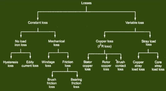
Copper Losses
Core Losses
Kh = Hysteresis constant depends upon the material
Bm = Maximum flux density
f = frequency
v = Volume of the core
t = thickness of the coreMechanical Losses
Stray Load Losses
Ques.63. A servo system must have ____
- Feedback system
- Power amplifier to amplify an error
- Capacity to control position or its derivative
- All options are correct✓
A servo system is defined here as the drive, motor, and feedback device that allow precise control of position, velocity, or torque using feedback loops. Examples of servomotors include motors used in machine tools and automation robots. Stepper motors allow precise control of motion as well, but they are not servos because they are normally run “open loop,” without tuning and without the need for stability analysis. The basic block Diagram of the Servo System is given below Amplifier:- The function of the amplifier is to amplify the servo error voltage e by some constant K, and to produce a defined output that causes the motor to move the load inertia to reduce the servo error. Feedback:- Input and feedback signals may take the form of voltages, currents, frequencies, temperature, etc., and appropriate transducers must be incorporated within the loop to enable the input and feedback terms to be added algebraically and to present the amplifier with an error voltage appropriate to its design. Precise Control:- The servo system must be supplied with position and/or velocity commands from a robot controller, which may control either single or multiple robot motors. The controller takes the position command received from a central computer and converts it to the necessary motor control signals. These signals precisely control motor position over time, thereby also controlling motor acceleration, run velocity, and deceleration.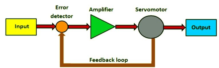
Ques.64. To neglect a voltage source, the terminals across the source are ____
- Open-circuited
- Short-circuited✓
- Replaced by some resistance
- Replaced by capacitance
An ideal voltage source does not have any internal resistance it means there is no resistance in series with the voltage source. So an ideal voltage source is having zero equivalent resistance. An ideal voltage source makes the circuit short-circuited. Similarly, if we have a zero resistive path in parallel with an ideal current source, the parallel path makes the current source open-circuited. An ideal current source has the infinite internal impedance
Ques.65. The best indication about the state of charge on a lead acid battery is given by
- Specific gravity of electrolyte✓
- Temperature of electrolyte
- Output voltage
- None of these
The lead-acid battery is the oldest and most mature among the all-battery technologies. Because of their large applications, lead-acid batteries have the lowest cost of all-battery technologies. This battery operates at an ambient temperature and has an aqueous electrolyte. Even though the lead-acid battery is relatively inexpensive, it is very heavy, with limited usable energy by weight (specific energy). The state of charge of a lead-acid battery can be determined by the specific gravity of the electrolyte (its weight compared to water). The specific gravity can be measured directly with a hydrometer or determined by the stabilized voltage. A hydrometer is a bulb-type syringe that will extract electrolytes from the cell. A glass float in the hydrometer barrel is calibrated to read in terms of specific gravity. A common range of specific gravity used on these floats is 1.160-1.325. The lower the float sinks in the electrolyte, the lower its specific gravity is. Measuring the specific gravity of a battery’s electrolyte with a hydrometer is the most accurate way to test the state of charge. This is true because the concentration of sulfuric acid changes as the battery is charged or discharged, and the change in concentration corresponds with a change in electrolyte density. Specific gravity is a measurement of the density of a liquid. A specific gravity of 1.260 in a lead-acid battery means that the battery is fully charged. As the battery is discharged, the specific gravity of the electrolyte falls to 1.120 for a state of charge of 0 percent.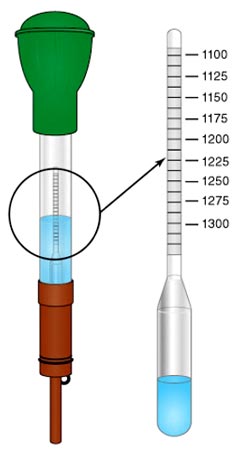
Ques.66. What should be the value of earthing resistance for large power stations?
- 5Ω
- 1Ω
- 0.5Ω✓
- 3Ω
Equipment Earthing
According to Rule 61 of Indian Electricity Rules 1956, it is obligatory to earth by the following points and apparatus used in the power system, where the voltage is more than 125 V:
- All the metal frames of motors, generators, transformers, and controlling equipment.
- The steel tower and steel tubular or rail poles carry overhead conductors.
- The metal flames of portable electrical equipment such as heaters, table fans, electric iron, refrigerator, air conditioners, vacuum cleaners, etc.
- Other metal parts such as conduits, switchgear casings, etc.
- Earth terminal of all the three-pin outlet sockets.
- The value of earthing resistance for large power stations should not be more than 0.5Ω
- In the case of concentric cables, external conductors, that is, armoring of such cables.
- Stay wires of overhead lines if the stay insulator is not provided.
In case of insulation failure, the primary objective of connecting all the above points and apparatus to earth is to release the charge accumulated on them immediately to earth so that the person coming in contact may not experience electric stock. The other objective is that a heavy current when flows through the circuit operate the protective device like., fuse or miniature circuit breakers, which opens the circuit.
[ninja_tables id=”28855″]
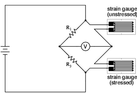
Ques.67. Dummy strain gauge is used in conjunction with the main strain gauge to ___
- Calibrate the system
- Compensate temperature effects✓
- Improve sensitivity
- Reduce strain on the gauge
The strain is defined as the deformation of materials caused by the action of stress. A body subjected to external forces is in the condition of both stress and strain. Stress cannot be measured directly. As there is a relationship between stress and strain, the effect of stress can be shown by the measurement of the strain. Thus, the stress occurring in a body can be computed if sufficient strain information is available. The measurement helps in knowing better about any structure, whether it is strong enough for the purpose or it may fail in use. The change in resistance of the strain gauge, when subject to strain, is usually converted into a voltage signal by the use of a Wheatstone bridge. A problem that occurs is that the resistance of the strain gauge also changes with temperature, and thus some means of temperature compensation has to be used so that the output of the bridge is only a function of the strain. This can be achieved by placing a dummy strain gauge in an opposite arm of the bridge, that gauge not being subject to any strain but only the temperature. If the temperature changes, both gauge resistances will change by the same percentage, and the bridge’s state of balance will remain unaffected. A popular alternative is to use four active gauges as the arms of the bridge and arrange them so that one pair of opposite gauges is in tension and the other pair in compression. This not only gives temperature compensation; it also gives a much larger output change when strain is applied. 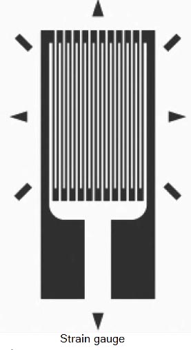
Ques.68. Attenuation in a network in decibels is equal to ______
- 0.735 x attenuation in nepers
- 0.367 x attenuation in nepers
- 2.332 x attenuation in nepers
- 8.686 x attenuation in nepers✓
Attenuation is the decrease in the signal amplitude over the length of the link. The longer the link and the higher the signal’s frequency, the greater the attenuation or loss will be. Attenuation is also expressed in nepers as the natural logarithm of the voltage or current ratio. The Neper is a logarithmic unit for ratios of measurements. 1db = 8.686 neper. Attenuation in dB = 0.868 × attenuation in neper
Ques.69. If a capacitor is charged by a square wave current source, the voltage across the capacitor is ____
- Square wave
- Triangular wave✓
- Step function
- Zero
The simplest way to generate a triangular wave is to apply a square wave to an RC network, . This is an integrator circuit, and the output is taken from across the capacitor. When the square wave switches positive, the capacitor charges through the resistor to the square wave voltage. As we know, the charge curve of a capacitor is not really a straight line, but it closely approximates a straight line for a portion of the curve. When the square wave switches to zero, the capacitor discharges through the resistor, producing a negative-going voltage. The resulting waveform approximates a triangular wave, but it is not linear enough for many applications. In many applications, the triangular wave must be linear. Greater linearity can be achieved by making the RC time constant very long, compared to the period of the square wave. This causes the capacitor to charge and discharge on only a short portion of the charge-discharge curve. or The voltage across the capacitor is (VC) = 1/C ∫i(t) dt Here the current source i(t) is the square wave which is a step function. Therefore, the voltage developed across the capacitor will triangular wave since the integration of the square wave is the triangular wave.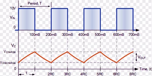
Ques.70. Absorbed moisture contents affect the dielectric strength ______
- Directly
- Indirectly✓
- Does not affect
- None of these
Materials that restrict or prohibit the flow of sound or heat or electricity through them are called insulators or insulating materials. They also avoid the accumulation of heat by proper distribution. The requirement of good insulating materials can be classified as electrical, mechanical, thermal, and chemical. Electrically the insulating material should have high resistivity to reduce the Leakage current and high dielectric strength to enable it to withstand higher voltage without being punctured or broken down. Further, the insulator should have a small dielectric loss. Dielectric properties:- The following important properties of insulation are taken into consideration in electrical insulating materials. (a) High Resistivity:- Electrical conductivity is the capacity of a material to conduct the electric current. Resistivity is the reciprocal of conductivity and is commonly measured as Insulation resistance. Thus a good insulator is that which possesses low conductivity or high resistivity. (b) High Dielectric strength:- The Dielectric strength of an insulating material determines its ability to resist puncture or breakdown by electric potentials. Hence the limiting intensity by electric field above which the insulators get punctured or ruptured is called the dielectric strength of the dielectric and is commonly expressed in volts per mm of the thickness of the material or volts per centimeter. The dielectric strength of a material can also be defined as the electrical field strength, that must be applied to cause a disruptive effect or discharge (arc or spark) or accumulate current through the body of the material. The dielectric strength is affected by a number of factors such as (a) Dielectric strength decreases as the thickness of the material increases (b) Dielectric strength decreases as the time of the application of electric current increases (c) Dielectric strength decreases as the frequency of the applied electric field is increased (d) Dielectric strength decreases in presence of humidity. (e) Dielectric strength decreases with an increase in temperature in case of air as an insulator. (c) Low Dielectric loss:- These are generally caused due to absorption of electrical energy and also by the leakage of current through the insulating material. The absorption of electrical energy. under an alternating electric field gives rise to the dissipation of the electrical energy in the insulating material, while leakage takes place as a result of conduction. The conduction is appreciable, however, only at high temperatures, otherwise, it is negligible. A good and ideal dielectric is that which does not absorb electrical energy and the charge of the capacitor is completely recovered when the electrical field is removed. A dielectric material, however, always causes some electrical energy loss, which is measured by the phase difference between the phase angle and 90 angles of an ideal capacitor. A perfect insulator is that has a phase angle of 90 and a loss angle of zero.