
Ques.71. The direction of rotation of a DC shunt motor is reversed by ___
- Reversing armature connections
- Interchanging the armature or field connection✓
- Adding resistance to the field circuit
- Reversing supply connections
The direction of rotation of a DC shunt motor can be reversed by interchanging the leads of either the field winding or the Armature Winding. Generally changing the direction of the field is easier, because it carries lesser current as compared to armature current. However, the reversal should not be done while the armature is excited.
Ques.72. The e.m.f. of a DC generator depends on _______
- Commutation
- Speed✓
- Frequency
- Brush contact drop
The voltage generated by the DC generator is given as Eg = PφZN/60A where P – Number of poles of the machine ϕ – Flux per pole in Weber. Z – Total number of armature conductors. N – Speed of armature in revolution per minute (r.p.m). A – Number of parallel paths in the armature winding. Hence from the above relation, the voltage generated is directly proportional to the speed of the rotation flux per pole, number of armature conductors, Number of poles Eg ∝ N Hence Generated voltage can be increased by increasing the speed of rotation.
Ques.73. A generating voltmeter uses _______
- Constant speed motor✓
- Variable speed motor
- Variable speed motor with a capacitor
- None of these
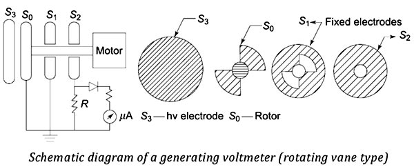
A generating voltmeter, also known as the rotary voltmeter, measures high direct voltages without loading the voltage source and without having any direct connections to the source. This is a variable capacitor electrostatic voltage generator that generates current proportional to the voltage to be measured. The device is driven by an external synchronous or constant speed motor and does not absorb power or energy from the voltage measuring source. For a constant angular frequency is, the current is proportional to the applied voltage V. More often, the generated current is rectified and measured by a moving coil meter. Generating voltmeter can be used for ac voltage measurements also provided the angular frequency ω is the same or equal to half that of the supply frequency. A generating voltmeter with a rotating cylinder consists of two exciting field electrodes and a rotating two pole armature driven by a synchronous motor at a constant speed n. The ac current flowing between the two halves of the armature is rectified by a commutator. If a time-variant capacitance system can be developed between the high voltage electrode and an earthed electrode, then the current flowing to earth will be a measure of the voltage. Generating voltmeters employ rotating sectors or vanes for variation of capacitance. The figure gives a schematic diagram of a generating voltmeter. The high voltage source is connected to a disc electrode S3 which is kept at a fixed distance on the axis of the other low voltage electrodes S0, S1, and S2. The rotor S0 is driven at a constant speed by a synchronous motor at a suitable speed (1500, 1800, 3000, or 3600 rpm). The rotor vanes of S0 cause the periodic change in capacitance between the insulated disc S2 and the hv electrode S3. The shape and number of the vanes of S0 and S1 are so designed that they produce sinusoidal variation in the capacitance. The generated ac current through the resistance R is rectified and read by a moving coil instrument. An amplifier is needed if the shunt capacitance is large or longer leads are used for connection to rectifier and meter. The instrument is calibrated using a potential divider or sphere gap. The meter scale is linear and its range can be extended by extrapolation. Generating Voltmeter
Working of Generating Voltmeter
Advantages of Generating Voltmeters
Limitations of Generating Voltmeters
Ques.74. Which of the following theorems enables a number of voltage (or current) sources to be combined directly into a single voltage (or current) source?
- Compensation theorem
- Reciprocity theorem
- Superposition theorem
- Millman’s theorem✓
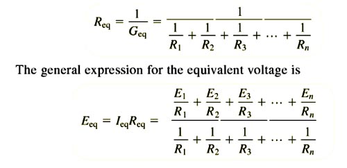
It is possible to combine the number of voltage sources or current sources into a single equivalent voltage or current source, using Millman’s theorem. Millman’s theorem is used to simplify circuits having several parallel voltage sources as. The statement of Millman’s theorem is, If n voltage sources V1, V2 ,……………………….Vn having internal Resistance (or series Resistance) R1, R2 ,……………………….Rn respectively are in parallel, then these sources may be replaced by a single voltage source of voltage Veq having a series impedance Req, Where Veq and Req is given as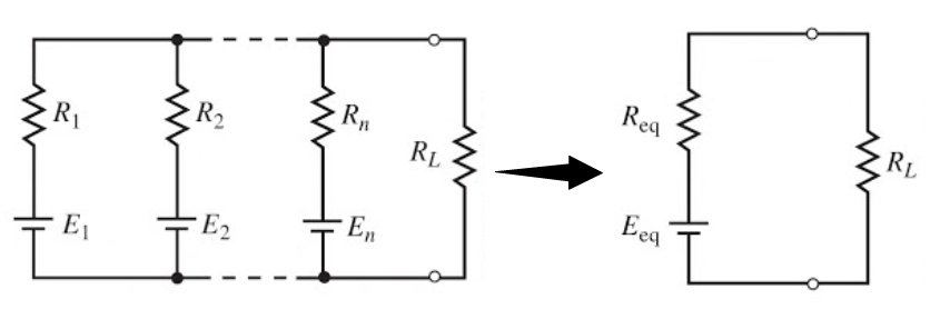
Ques.75. During charging, the specific gravity of the electrolyte of a lead-acid battery ____
- Decreases
- Remains the same
- Increases✓
- None of these
The lead-acid battery is the oldest and most mature among the all-battery technologies. Because of their large applications, lead-acid batteries have the lowest cost of all-battery technologies. This battery operates at an ambient temperature and has an aqueous electrolyte. Even though the lead-acid battery is relatively inexpensive, it is very heavy, with limited usable energy by weight (specific energy). The state of charge of a lead-acid battery can be determined by the specific gravity of the electrolyte (its weight compared to water). The specific gravity can be measured directly with a hydrometer or determined by the stabilized voltage. A hydrometer is a bulb-type syringe that will extract electrolytes from the cell. A glass float in the hydrometer barrel is calibrated to read in terms of specific gravity. A common range of specific gravity used on these floats is 1.160-1.325. The lower the float sinks in the electrolyte, the lower its specific gravity is. Measuring the specific gravity of a battery’s electrolyte with a hydrometer is the most accurate way to test the state of charge. This is true because the concentration of sulfuric acid changes as the battery is charged or discharged, and the change in concentration corresponds with a change in electrolyte density. Specific gravity is a measurement of the density of a liquid. The specific gravity of 1.260 in a lead-acid battery means that the battery is fully charged. As the battery is discharged, the specific gravity of the electrolyte falls to 1.120 for a state of charge of 0 percent. A fully charged battery has all of the sulfates in acid. As the battery discharges, some of the sulfates begin to appear on the plates. The acid becomes more dilute and its specific gravity drops as water replaces more of the sulfuric acid. A fully discharged battery has more sulfate in the plates than in the electrolyte. Please note that the hydrometer float sinks lower in the electrolyte as the specific gravity becomes lower. A hydrometer reading should never be taken immediately after water is added to the cell. The water must be thoroughly mixed with the underlying electrolyte.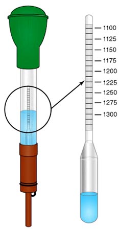
Ques.76. What type of earthing is used by transmission lines?
- Plate earthing
- Rod earthing
- Strip earthing
- All of the above✓
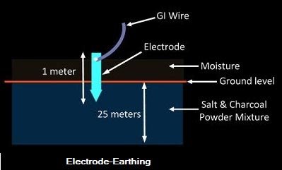
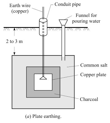
The process of connecting metallic bodies of all the electrical apparatus and equipment to the huge mass of earth by a wire of negligible resistance is called earthing. or Earthing is to connect any electrical equipment to earth with a very low resistance wire, making it to attain earth’s potential. The wire is usually connected to copper. When a body is earthed, it is basically connected to the huge mass of the earth by a wire having negligible resistance. Therefore, the body attains zero potential, that is, the potential of the earth. This ensures that whenever a live conductor comes in contact with the outer body, the charge is released to the earth immediately. Good Earthing must have low impedance enough to ensure that sufficient current can flow through the safety device so that it disconnects the supply ( <0.4 sec ). The fault current is much more than the full load current of the circuit which melts the fuse. Hence, the appliance is disconnected automatically from the supply mains. According to Indian Electricity Rule No,61 the following equipment are to be connected to the earth. The conductors used for earthing purposes are copper or galvanized iron wire. However, since the conductor used for earthing must have high conductivity, copper is preferred. The conductor used should have sufficient diameter in order to carry the fault current safely. The earthing conductor should be installed in such a way that it should not get damaged or cut accidentally. It can be fixed to the equipment with the help of clamps and saddles. When fuses are used, the earth loop impedance should be low enough so as to allow 3 times the current on a short circuit and 1.5 times the operating current when circuit breakers are used. The earth electrode should make very good contact with the general mass of the earth. Different methods of earthing are Wire or strip earthing is applied at the places (rocky soils where it is difficult to dig pits of the desired depth. Usually a copper wire of 5 SWG of enough length is buried in horizon trenches of depth. Rod earthing is used at the sandy soil. Since excavation is not required, it is cheaper. A solid rod of galvanized iron of diameter 1.9 cm is laid vertically into the earth up to a depth of 200 to 300 cm. The conductor is tied to the rod with small clamps. Pipe earthing is the common method of earthing done using G.l. of diameter 3.8 cm. A pit of about 40 cm square area and 4 to 5-meter depth is dug in the soil. To increase the dampness and moisture, charcoal and salt are filled in the pit in alternate layers up to about two meters from the bottom. Earth pipe can be protected from mechanical damage by covering it with cement concrete work. A funnel with mesh can also be pros vided to pour water. In the plate earthing a pit of about 3 melees depth is dug. The em electrode use may be a copper plate having a dimension 60 cm x 60 cm x 3.18 mm. (In the case of GI plate, the dimension is 60 cm x 60 cm x 6.36 mm). After placing the electrode in the pit layers of charcoal and salt are used to fill the space around it. The layers of charcoal shall be placed immediately over the plate, and thereafter, successive layers of salt and charcoal are laid to keep the surroundings sufficiently moist. Note: Pipe earthing and plate earthing is considered to be the best as they have a reasonably low value of earth resistance. Advantages of Earthing:
Methods of earthing:
Wire or strip earthing:
Earthing rods
Pipe earthing:
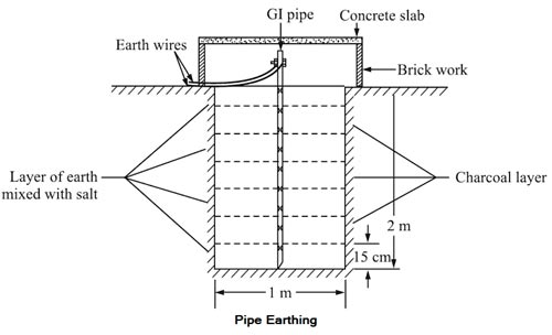
Plate Earthing:
Ques.77. The use of thermocouple meters for AC measurement leads to a meter-scale which is _____
- Linear
- Square law✓
- Logarithmic
- Exponential
THERMOCOUPLE INSTRUMENTS A thermocouple consists of two dissimilar metals or wires forming a junction. It is a temperature measuring device that produces the voltage when its junction is heated by the operating current. The voltage produced is in proportion to the temperature of the junction and the output of the thermocouple is delivered to a sensitive DC PMMC microammeter. They are most commonly used as temperature sensors for control and measurement. Thermocouples also convert temperature gradient or heat energy into electrical energy. A thermocouple instrument is a combination of a thermocouple element and a PMMC instrument. Since the operation of the instrument is based on the thermocouple element, it is named so. It can be used for DC as well as AC applications and can measure high-frequency voltages and currents very accurately. Principle The thermocouple works upon the principle that when a junction between two different metals is heated, different work functions of the metals produce different temperatures at their ends. This, in turn, yields an electric quantity, that is, the voltage in proportion to the junction temperature. This effect is referred to as the Seebeck effect and forms the basis of the thermocouple instruments. Constructional details The two different wires when joined together, form a thermocouple. Different combinations of alloys can be used to form the wires of thermocouples, such as copper-constantan, platinum-rhodium, iron-constantan, and chrome-alumel. The junction of the thermocouple is either welded directly to the heater or thermally connected to it using a ceramic bead as shown in Figure. The connected end of the wires is termed as the hot junction or sensing junction while the other end is termed a cold junction. The thermocouple instrument is connected to an electric circuit to perform the measurement. The circuit current (to be measured) provides the required heat at the junction. The temperature difference between the hot and cold junctions determines the amount of voltage or emf generated at the output of the thermocouple. This voltage is very low, in the range of milli-volts. It can be regarded as a measure of the root mean square (RMS) value of the operating current since the current heats up the heater element in proportion to its RMS value. This voltage is used to indicate the amount of temperature generated at the junction. The scale is essentially a milli-volt scale on which the standard value of reference temperature at the cold junction is marked as 32° F. that is, 0°C.
Ques.78. To a highly inductive circuit, a small capacitance is added in series. The angle between voltage and current will _______
- Increase
- Decrease✓
- Remain nearly the same
- Become in-determinant
For an Inductive Resistive circuit, the phase φ is given as tan φ = XL/R The current lags the voltage by approx 90° When a capacitor is added to the circuit such that XL > XC the phase angle φ is given as tan φ = XL − XC/R Now the capacitance will compensate the current lags in the circuit, therefore, the angle between the voltage and current will be reduced.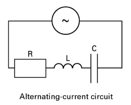
Ques.79. The internal voltage drop of a voltage source ____
- Is the highest when no load is applied
- Does not influence the terminal voltage
- Depends upon the internal resistance of the source✓
- Decreases with increase load current
The load current supplied by any voltage source, whether it be a cell or battery, a generator, or a transformer, also pass through the voltage source itself. This is because the voltage source is part of the complete circuit around which the load current flows. In other words, the ‘inside’ of the voltage source is in series with its external load. So what exactly do we mean by the ‘inside’ of a voltage source? Well, in the case of a generator, for example, the load current must also pass through the windings (coils) in which the voltage is generated by the rotating machine. In the case of a generator, the internal resistance is the resistance of the windings within which the voltage is generated. In the case of a cell or battery, the internal resistance is made up of the combined effect of two components: the first is due to the resistivity of the internal conducting parts (the electrodes and any metallic connections), and the second, called ‘ionic resistance’, is due to the electrochemical opposition within the electrolyte. The first increases as the cell’s electrodes dissolve (in the case of nonchargeable cells) because their effective cross-sectional area reduces; the second increases as the cell de-energizes. The internal resistance of a fully energized, healthy cell is typically expressed in milliohms but, as the cell deteriorates, its internal resistance may rise markedly. A cell’s internal resistance will also vary according to its state of charge. The internal resistance of a generator’s windings is also low but will increase somewhat when the windings are hot (see the chapter on the effect of temperature on resistance), whenever the machine is running for prolonged periods. The effect of the voltage source’s internal resistance is to cause an internal voltage drop (IR;) to occur within the voltage source itself. The direction of this voltage drop is such that it always acts to oppose the electromotive force of the voltage source and to reduce the value of the terminal voltage applied to the load. The larger the load current, the larger the corresponding internal voltage drop, and the loiter the terminal voltage applied to the load. The voltage appearing across the load is called the terminal voltage (U), and is the difference between the voltage source’s electromotive force (E) and its internal voltage drop (lR), that is: U= E − IR For any given load resistance, the greater the internal resistance, the lower the voltage source’s terminal voltage. For any given internal resistance, the lower the load resistance, the taller the voltage source’s terminal voltage. If there is no load connected to the voltage source, then no-load current will flow, and there will be no internal voltage drop. the voltage appearing across the voltage source’s terminals under this condition is called its open-circuit voltage or no-load voltage which exactly equals the electromotive force (e.m.f.) of that source. A voltage source’s open-circuit, or no-load, voltage corresponds to its electromotive force.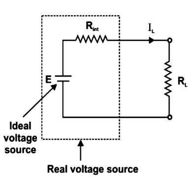
Ques.80. Which of the following pairs of arrows show the wrong direction of the forces between the charges?
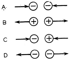
- A✓
- B
- C
- D
As we know that the like charge repels each other and opposite charge attracts. In figure A the two negative charges are attracting each other which is impossible.