
Ques.81. If the current in the armature of DC series motor is reduced by 5%, the torque of the motor will become
- 50% of the previous value
- 25% of the previous value✓
- 90.25 % of the previous value
- 125% of the previous value
In DC series Motor, the torque is directly proportional to the square of the armature current T ∝ Ia2 So if the armature current is reduced to 5% then torque is T = 52 T = 25%
Ques.82. The speed of a DC motor is _____
- Directly proportional to back e.m.f. and inversely proportional to flux✓
- Inversely proportional to back e.m.f. and directly proportional to flux
- Directly proportional to e.m.f. as well as to flux
- Inversely proportional to e.m.f. as well as flux
Voltage Equation of DC Motor The voltage equation of the DC Motor is given as V = Eb + IaRa The voltage V applied across the motor armature has to The above equation can also be written as Eb = V − IaRa When the armature of a d.c. the motor rotates under the influence of the driving torque, the armature conductors move through the magnetic field and hence e.m.f. is induced in them as in a generator. The induced e.m.f. acts in opposite direction to the applied voltage V (Lenz’s law) and is known as back or counter e.m.f. Eb. ${E_b} = \dfrac{{P\Phi ZN}}{{60A}}$ Where P – Number of poles of the machine ϕ – Flux per pole in Weber. Z – Total number of armature conductors. N – Speed of armature in revolution per minute (r.p.m). A – Number of parallel paths in the armature winding. From the above equation, it is clear that the EMF of DC Motor is Directly proportional to the Number of poles of the machine (P), Flux per pole in Weber (ϕ), Total number of armature conductors(Z), and Speed of armature (N) From the voltage equation and Back EMF equation, we can conclude that $\begin{array}{l}\dfrac{{P\Phi ZN}}{{60A}} = V – {\rm{ }}{I_a}{R_a}\\\\N = \dfrac{{V – {\rm{ }}{I_a}{R_a}}}{\Phi } \times \left( {\dfrac{{60A}}{{PZ}}} \right)r.p.m\\\\{E_b} = V – {\rm{ }}{I_a}{R_a}\\\\\therefore N = K\dfrac{{{E_b}}}{\Phi }\end{array}$ The above equation shows that speed is directly proportional to back e.m.f. E b and inversely to the flux Φ N ∝ Eb /Φ. $N = \dfrac{{{E_b}}}{\Phi } \propto \dfrac{{V – {\rm{ }}{I_a}{R_a}}}{\Phi }$ But as the value of armature resistance Ra and series field resistance, Rse is very small, the drop IaRa and Ia (Ra + Rse) is very small compared to applied voltage V. Hence, neglecting these voltage drops the speed equation can be modified as, $N \propto \dfrac{V}{\Phi }$
(i) overcome the back e.m.f. Eb and
(ii) supply the armature ohmic drop IaRaBack EMF of DC Motor
Ques.83. Centrifugal Methods of reconditioning transformer oil is effective for removal of _____
- Water✓
- Dissolved gases
- Solid impurities
- All options are correct
Transformer oil: Transformer cores and chokes are commonly immersed in oil, known as transformer oil which acts to some extent as an insulator but chiefly as a cooling medium. This is also used in many other apparatuses such as switches and circuit breakers, reactors, rheostats, etc. The transformer oil is obtained after distilling off the lighter fractions (gasoline, petroleum, naphtha, and kerosene) in the process of crude oil distillation. The oil thus obtained is first treated with sulphuric acid, then treated with alkali to neutralize the acid, thoroughly washed with water, filtered and dried. Contamination and Purification of transformer oil: Many impurities such as water, fiber, resins, carbon particles, epic., may get into the oil due to imperfect purification at the plant. They may also get into the oil during transportation and storage or while in service (aging). Water may exist as dissolved or as tiny bubbles suspended in the oil. The presence of these impurities decreases the breakdown voltage. The oil is purified in the following ways: (i) The oil is boiled, preferably in a vacuum, to evaporate the water contained in the oil. (ii) Since the impurities including water are heavier than oil these can be removed from the oil by quic}dy rotating the oil in the centrifuge. The impurities are pressed against the sides of the vessel by centrifugal force. (iii) The solid implies are also removed by filtering through special filter cardboard under pressure. Adsorbents are added whose particles readily adsorb the products of aging and moisture on their surface. The heated oil can be thoroughly mixed with the crushed adsorbent and then filtered (contact method) or can be passed through a thick layer of the adsorbent (percolation). The adsorbent used for transformer oil are is mostly artificial products such as silica gel and alumina or special types of clays, Fuller’s earth, molding clay, etc.
Ques.84. What is called the electromotive force (e.m.f.) of a voltage source?
- Terminal voltage when the load is applied
- Internal voltage when no load is applied✓
- Energy Per unit charge✓
- The electric pressure provided to the load
Note:- Both options are correct Emf is not a force at all; it is a special type of potential difference. To be precise, the electromotive force (emf) is the potential difference of a source when no current is flowing. Units of emf are volts. If there is no load connected to the Voltage source, then no load current will flow, and there will no internal voltage drop. The voltage appearing across the voltage source’s terminals under this condition called its open-circuit voltage or no-load voltage which exactly equals the electromotive force (e.m.f. of that source). A voltage source open-circuit, or no-load, voltage corresponds to its electromotive force. The electromotive force (e.m.f.) of a cell is the electrical energy per unit charge created in the cell. The unit of e.m.f. is the volt, equal to 1 joule per coulomb. Note that the volt is also the unit of potential difference. However, the potential difference is defined as electrical energy delivered per unit charge, whereas e.m.f. is electrical energy created per uni charge. Thus a source of e.m.£ is a source of electrical energy, whereas a potential difference is a ‘sink’ of electrical energy.
Ques.85. The main purpose of using the core in a transformer is to _______
- Decrease iron losses
- Prevent eddy current loss
- Eliminate magnetic hysteresis
- Decrease reluctance of the common magnetic circuit✓
When a coil is wound around a nonmagnetic material such as wood or plastic, it is known as an air core magnet. When a coil is wound around a magnetic material such as iron or soft steel, it is known as an iron core magnet. The addition of magnetic material to the center of the coil can greatly increase the strength of the magnet. If the core material causes the magnetic field to become fifty times stronger, the core material has a permeability of 50.
Permeability is a measure of a material’s ability to become magnetized. The number of flux lines produced is proportional to the ampere-turns.
The magnetic core material provides an easy path for the flow of magnetic lines, in much the same way that a conductor provides an easy path for the flow of electrons. This permits the flux lines to be concentrated in a smaller area, which increases the number of lines per square inch or square centimeter.
Another common magnetic measurement is reluctance. Reluctance is resistance to magnetism. A material such as soft iron or steel has high permeability and low reluctance because it is easily magnetized. A material such as copper has low permeability and high reluctance.
If the current flow in an electromagnet is continually increased, the magnet will eventually reach a point at which its strength will increase only slightly with an increase in current. When this condition occurs, the magnetic material is at a point of saturation. Saturation occurs when all the molecules of the magnetic material are lined up. Saturation is similar to pouring five gallons of water into a five-gallon bucket. Once the bucket is full, it cannot hold any more water. If it became necessary to construct a stronger magnet, a larger piece of core material would be required.
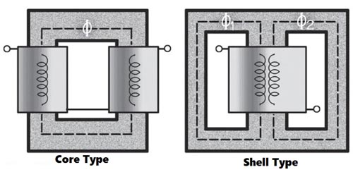
Transformer Core
In the case of a simple, two-winding transformer, its core is an example of a homogeneous magnetic circuit, the purpose of which is to efficiently link the magnetic flux created by its primary winding with its secondary winding. There are two different types of transformer core design: ‘core type’ and ‘shell type’). By using a low-reluctance (‘sort’) ferromagnetic material (typically, silicon steel), the maximum flux density is assured, with minimum remenance, and with a minimum energy requirement – thereby maximizing the efficiency of the transformer.
Ques.86. What is the dimension of the copper strips used for the strip earthing?
- 25 mm × 1.6 mm✓
- 25 mm × 3 mm
- 30 mm × 4 mm
- 30 mm ×3 mm
Methods of earthing:
Different methods of earthing are
- Wire or strip earthing
- Rod earthing
- Pipe earthing
- Plate earthing
Wire or strip earthing:
This system of earthing employs the use of 5 SWG Standard wire gauge) copper wire or strip of cross section not less than 25 mm x 1.6 mm. The strips or wires are buried in horizontal trenches. This type of earthing is used where the earth bed has rocky soil and excavation work is difficult.
Earthing rods
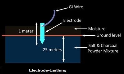
Rod earthing is used in the sandy soil. Since excavation is not required, it is cheaper. A solid rod of galvanized iron of diameter 1.9 cm is laid vertically into the earth up to a depth of 200 to 300 cm. The conductor is tied to the rod with small clamps.
Pipe earthing:
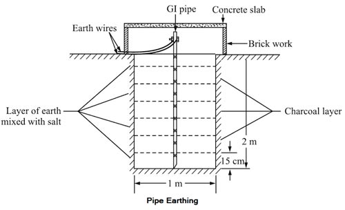
Pipe earthing is the common method of earthing done using G.l. of diameter 3.8 cm. A pit of about 40 cm square area and 4 to 5-meter depth is dug in the soil. To increase the dampness and moisture, charcoal and salt are filled in the pit in alternate layers up to about two meters from the bottom. Earth pipe can be protected from mechanical damage by covering it with cement concrete work. A funnel with mesh can also be pros vided to pour water.
Plate Earthing:
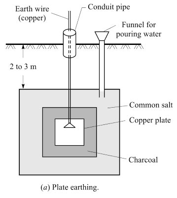
In the plate earthing a pit of about 3 melees depth is dug. The em electrode use may be a copper plate having a dimension 60 cm x 60 cm x 3.18 mm. (In the case of GI plate, the dimension is 60 cm x 60 cm x 6.36 mm). After placing the electrode in the pit layers of charcoal and salt are used to fill the space around it. The layers of charcoal shall be placed immediately over the plate, and thereafter, successive layers of salt and charcoal are laid to keep the surroundings sufficiently moist.
Note: Pipe earthing and plate earthing is considered to be the best as they have a reasonably low value of earth resistance.
Advantages of Earthing:
- It protects the operating personnel from the danger of shock in case they come in contact with the charged frame due to defective insulation.
- It maintains the line voltage constant under unbalanced load conditions.
- Protect the electrical equipment.
- Protect large buildings and all machines fed from overhead lines against lightning.
- Serve as a return conductor in electric traction system and communication.
- Avoid the risk of fire in an electrical installation system.
Ques.87. Which one of the following is the best method of measurement of the temperature of hot bodies radiating energy in the visible spectrum?
- Thermocouple
- Thermopile
- Optical pyrometer✓
- Barometer
A pyrometer is a device for measuring very high temperatures and uses the principle that all substances emit radiant energy when hot, the rate of emission depending on their temperature. The measurement of thermal radiation is, therefore, a convenient method of determining the temperature of hot sources and is particularly useful in industrial processes. There is two main types of pyrometer, namely the total radiation pyrometer and the optical pyrometer.
Pyrometers are very convenient instruments since they can be used as a safe and comfortable distance from the hot source. Thus applications of pyrometer are found in measuring the temperature of molten metals, the interiors of furnaces, or the interiors of volcanoes. Total radiation pyrometers can also b used in conjunction with devices that record and control temperature continuously.
Total radiation pyrometers are used to measure temperature in the range 700°C to 2000°C.
Optical pyrometers may be used to measure temperatures up to, and even in excess of, 3000°C.
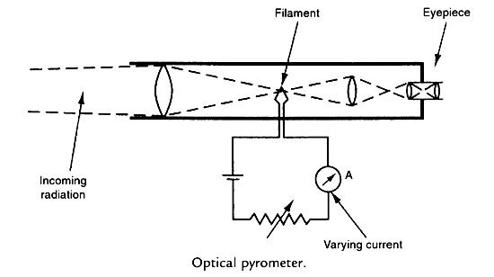
Optical Pyrometer
The optical pyrometer is designed to measure temperatures where the peak radiation emission is in the red part of the visible spectrum, that is, where the measured body glows a certain shade of red according to the temperature. The instrument contains a heated tungsten filament within its optical system. The current in the filament is increased until its color is the same as the hot body: under these conditions, the filament apparently disappears when viewed against the background of the hot body. Temperature measurement is therefore obtained in terms of the current flowing in the filament. As the brightness of different materials at any particular temperature varies according to the emissivity of the material, the calibration of the optical pyrometer must be adjusted according to the emissivity of the target.
Ques.88. The transient currents are due to ______.
- Voltage applied to circuit
- Resistance of the circuit
- Impedance of the circuit
- Change in stored energy in inductors and capacitance✓
Transient is any sudden change in the system caused by generator shifting, faults, outages, addition or removal of a heavy load or any switching operation in the system. Transients are non-steady-state time variations of voltages and currents which occur as a result of switching circuit elements and (or) changing interconnections of electric circuits. The transients occur because of the presence of energy storage elements (i.e., inductors and capacitors). As we know that the potential difference across a capacitor cannot change instantaneously and the current through an inductor cannot change suddenly. If therefore, when a circuit containing capacitance or/and inductance is operating in the steady-state and conditions change for some reason, requiring the current and voltage values to change, there will be a finite period of time during which these changes take place. This period is called a period of transient operation. Two obvious examples of transient operation are (1) when a circuit containing capacitance or inductance is initially switched on and (2) when such a circuit, having been operating in the steady-state for some time, is suddenly switched off. These transient conditions are associated with the changes in the energy stored in the capacitor or the inductor, and circuits containing either of these elements are called single energy circuits. Circuits containing both of these elements are called double energy circuits. Because there is no energy stored in purely resistive circuits, currents and voltages in such circuits are able to change without periods of transient operation (i.e. instantaneously).
Ques.89. Efficiency is _______
- The difference between power input and output
- The relation of power input to power output
- The relation of power output to the power losses
- The percentage of power output compared with the input✓
In any machine, the power available at the output is less than that which is put in because losses occur in the machine. The losses may result from friction in the bearings, wind resistance to moving parts, heat, noise or vibration. The ratio of the output power to the input power is known as the efficiency of the machine. The symbol for efficiency is the Greek letter ‘eta’ (η). in general, η = Power Output/ Power Input Since efficiency is usually expressed as a percentage we modify the general formula as follows: %η = Power Output/ Power Input × 100
Ques.90. In the electrical circuit diagram as shown below the value of current in 3Ω resistor is _____
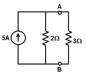
- 2 Ampere✓
- 0.2 Ampere
- 1.6 Ampere
- 1 Ampere
Applying current divider rule in the following circuit I3ohm = ITotal R1 /(R1 + R2 ) I3ohm = 5 × 2/( 2 + 3) I3ohm = 2 A