SSC JE Electrical question paper with solution 2016 -Set-3
Ques.1. The waveform of the armature m.m.f. in DC machine is
- Triangular✓
- Square
- Rectangular
- Sinusoidal
The armature mmf of a distributed armature winding of a dc machine is triangular in shape as shown in Fig. In a D.C. machine, the armature M.M.F. wave has its maximum value at fixed points between the main poles, and its chief effect is to increase the flux density on one side of the pole and reduce it on the other At GNA (Geometrical neutral axis) MMF Attends it’s maximum value MMF and at MNA ( Magnetic neutral axis) MMF Attends zero value, it is alternating in nature. At MNA axis the armature conductors are situated in parallel with the field flux thus induced EMF is zero at that time and at GNA axis the armature conductors are situated at 90 ° with the field fluxes, between MNA and GNA the armature MMF slowly rise as the angle between an armature conductor and field flux increases the MMF induced on that conductor increases thus it creates a triangular form of armature MMF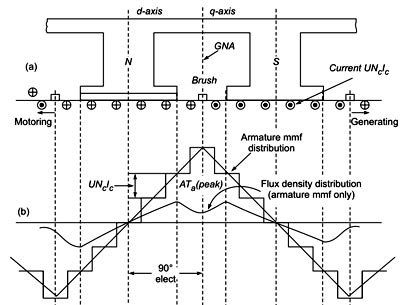
Ques.2. The current flowing in the conductors of a DC motor is
- D.C
- A.C✓
- D.C as well as A.C
- Transients
In a DC motor, a conductor (armature) is located between the north and south poles of a stationary magnet (field structure). A commutator is used to reverse the direction of the current, helping transmit current between the power source and armature. The armature is a cylindrical device attached to a driveshaft that is designed to become an electromagnet when current is passed through it. During operation, the armature rotates through the magnetic fields. At set intervals, the rotation cuts across the magnetic fields, reversing current flow. This process occurs on each half rotation of the armature. The field structure provides a magnetic field for the armature to move through. Magnetic fields are composed of lines of force. In DC motors, the terms field structure, field magnet, and field coils may be used to represent the stationary magnet. When the D.C supply passes through the conductor in a DC motor, the conductor becomes an electromagnet and generates another magnetic field inside the original lines of force. As the twin fields increase in intensity, they strengthen each other and push against the conductor. The current and these strong magnetic fields determine the direction of rotation in a DC motor. Note:- If A.C supply is given to the DC motor then the Series Connection: Parallel connection: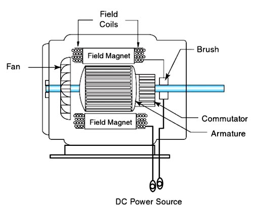
where k = number of poles and the number of turns in the winding.
Φ = flux per pole
i = current.
Therefore, Torque = k × Ia2
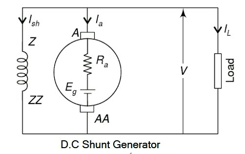
Ques.3. DC shunt generator has
- Slightly drooping characteristic curve✓
- Appreciably rising characteristic
- Constant voltage characteristic
- Appreciably falling characteristic
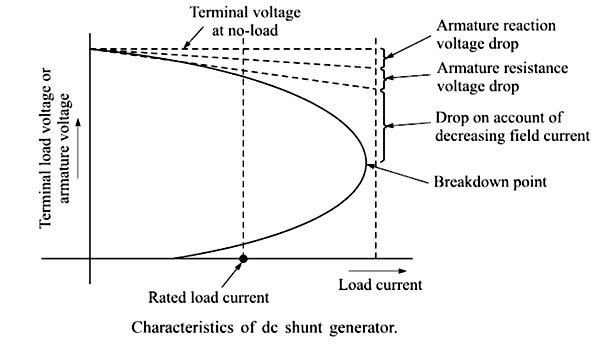
The electrical equivalent circuit of a long shunt compound generator is shown in Fig. The shunt field winding is connected across the series combination of armature and series field windings and across the load. This is characterized by the fact that the series field current equals the armature current. The terminal voltage of the generator decreases on loading. This is because of In the case of a dc shunt generator, the field circuit is connected directly across the armature. With the increase in the load current, the voltage drops as a result of armature reaction and internal resistance of the armature circuit are increased, and therefore the terminal voltage decreases. Hence the field current decreases. As a result, the terminal voltage drops further. At no-load, the terminal voltage is the same as the generated voltage. The effects of armature reaction, armature circuit voltage drop, and the decrease in field current are all shown in Figure. against the increase in load current. The effects of both the armature reaction and the armature resistance voltage drop are shown as dashed straight lines in Figure. These dashed lines represent linear voltage decreases directly proportional to the increase in load current. The drop owing to decreased field current is represented by the curved line since it depends on the degree of field flux saturation at that value of the load. It can be seen from Figure that the terminal voltage decreases with load current only to a small extent up to its rated load current value. Thus, the shunt generator produces a fairly constant output voltage with the application of load. If the further application of load continues, it causes the generator to reach a breakdown point where the armature reaction effect becomes so severe that the terminal voltage drops to a great extent and as a result, the generator cannot draw any larger load current. The load current, in fact, also drops.Characteristics of DC Shunt Generator
Ques.4. How should a fuse be installed in a circuit to ensure proper operation?
- Parallel to the load
- Series with the load✓
- Either way possible
- At the ground point
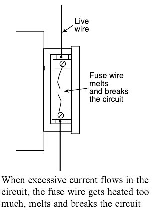
Fuse is the current interrupting device that breaks or opens the circuit (in which it is inserted) by fusing the elements when the current in the circuit exceeds a certain value. Fuse is the simplest and cheapest device used for interrupting an electrical circuit under the condition of short-circuiting, or excessive overload, current magnitudes. A fuse is a safety device having a short length of a thin, tin-plated copper wire having a low melting point, which melts and breaks the circuit if the current exceeds a safe value. The thickness and length of the fuse wire depend on the maximum current allowed through the circuit. An electric fuse works on the heating effect of current. The fuse for protecting our domestic wiring is fitted just above our main switch on the switchboard. A fuse wire is connected in series in the electric circuits so that current flowing through the conductor to any load must also pass through the fuse. The main fuse in domestic wiring consists of a porcelain fuse holder H having two brass terminals T1 and T2 in it. This is connected in the live wire. The other part of the fuse is a removable fuse grip G which is also made of porcelain. The fuse grip has a fuse wire fixed in it. When fuse grip is inserted in the fuse holder as shown in Figure, then the circuit of our domestic wiring is completed. So, under normal circumstances when the current is within the limit, then the fuse wire is intact and electric current is available in our wiring. When a short circuit takes place, or when overloading takes place, the current becomes large and the fuse wire too much. Since the melting point of fuse, wire is much lower than copper wires, the fuse wire melts and breaks the circuit as shown in Figure. When the fuse wire breaks, the electricity supply is automatically switched off before any damage can be done to the rest of the wiring (or the electric appliances being used). We will now give some important points about the fuse wire to be used in electrical circuits. First of all, we should know why we use a thin wire as a fuse wire and not a thick wire. We use a thin wire in a fuse because it has a much greater resistance than the rest of connecting wires. Due to its high resistance, the heating effect of current will be much more in the fuse wire than anywhere else in the circuit. This will melt the fuse wire whereas other wirings will remain safe. We should not use a thick wire as a fuse wire because it will have low resistance and hence it will not get heated to its melting point easily. The fuse wire is usually made from tin-plated copper wire having a low melting point so that it may melt easily. A pure copper wire cannot be used as a fuse wire because it has a high melting point due to which it will not be easy when a short circuit takes place. Fuse wire is made with an alloy of lead and tin having a low melting point and low resistance (although the resistance of fuse wire is higher than that of electrical appliances). If due to any malfunction or fault, excessive current begins to flow through the circuit, the fuse wire immediately melts due to the heat generated by the flowing current. The circuit is broken and the excess current, which may damage equipment is prevented from flowing. It is used for Overload and for short-circuit protection in high voltage (upto 66 kV) and for low Voltage (upto 120 V – 240 V) installations/circuits. Characteristics of a fuse are:-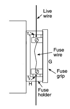
Ques.5. The open-loop control system is one in which
- The output is dependent on the control input
- The output is independent of the control input✓
- Only system parameters have an effect on the control output
- None of these
When the action of the system is independent of the output i.e the output has no influence or effect on the control action of the input signal then the system is called the open-loop control system. An Open-loop system is also called the non-feedback system. There are several limitations of open-loop systems which include: slow system response, poor disturbance rejection, poor tracking under uncertainties, high sensitivity to system parameter errors (e.g., errors in plant or controller gains), and high sensitivity to changes in calibration errors (hence recalibration is usually necessary).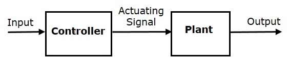
Ques.6. Which among these is a type of internal wiring?
I. Cleat wiring
II. Conduit wiring
III. CTS wiring
- Only I
- Only II
- Both II & III
- I, II & III✓
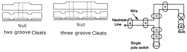
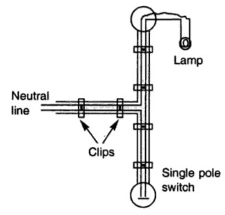
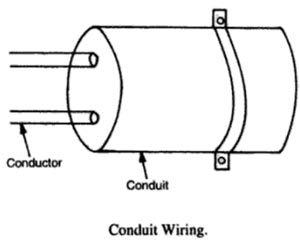
Electrical wiring is done in residential and commercial buildings to provide power for lights, fasts, pumps, and other domestic appliances are known as domestic wiring. There are several wiring systems in practice such as tree systems and distribution systems. The following are the different types of wiring systems used for domestic electrical installation. This system of wiring is the cheapest one. This system is used for insulated cables like rubber insulated cable, PVC cable etc. The cables are run over cleats made of porcelain. The cleats are generally in pairs having the bottom and top halves. The bottom half is grooved to receive the wire and the top is for cable grip. Initially, the bottom and top cleats are fixed on the wall loosely according to the layout. Then the cable is drawn, tensioned and the cleats are tightened by a screw. Cleats are fixed at regular intervals not exceeding 0.6 m Apart. This wiring is suitable for temporary installations where cost is the main criterion. This system is very widely used. In such wiring, the wires used are sheathed with the tough rubber of P.V.C. wires and they are clipped on the wooden button with clips. The button is fixed on the wall or ceiling. This wiring is suitable for damp climates, but cannot withstand much heat and so is not suitable for places of very hot weather and there is also the danger of mechanical damage and fire hazard. C.T.S. wires are not suitable for outdoor use. Therefore, they should not be exposed to direct sunlight and where there are corrosive acid fumes. Clips used are of the following two types : In conduit wiring, wires are carried through steel or iron pipes giving good protection from mechanical injury or fire risks. This system is the best and most desirable system of wiring for workshops and public buildings. It gives a very good appearance when concealed. In this wiring, the pipes are cut with the hacksaw and are threaded tee junction box etc., and are then fixed on the walls on wooden gutties or plugs with saddles. Then wires are drawn with the help of fish wire (steel wire). Nowadays P.V.C. conduit pipes are also available which do not require threading. Jointing is done with a special mode solution. These are flexible and can be bent easily. For concealed wiring, the pipes are directly buried in the wall and roofs, and then wires are drawn through them.Types Of wiring
Cleat Wiring
Advantages of Cleat Wiring:
Disadvantages of Cleat Wiring:
PVC wiring or CTS or TRS wiring system:
Advantages of CTS or TRS wiring system
Disadvantages of CTS or TRS wiring system
Conduit wiring system
Advantages of Conduit Wiring Systems
Disadvantages of Conduit Wiring Systems
Ques.7. If the range of an analog transducer is 0 to 10 V, then for a resolution of 5 mV, the bits of ADC will be
- 8
- 10
- 11✓
- 12
The output Voltage of ADC is given as; Vout = K × Digital Input Digital Input = Number of steps = ( 2n – 1) VOut = K( 2n – 1) K: resolution = 5mV = 5 × 10⁻³ n: number of bits = ? 10 = 5× 10 – 3 (2n – 1) 2n = 2001 n =11 bits (approximate)
Ques.8. The standing wave ratio of a 75Ω transmission line used to feed a 300Ω resistive load will be
- 4✓
- 3
- 2
- 1
The ratio between the maximum and minimum voltage (or current) is called the standing wave ratio (SWR) and is defined as SWR = Vmax/Vmin = Imax/Imin = (1 + ΓZ)/(1 − ΓZ) ————1 Where ΓZ = Reflection coefficient = (ZL − Zo) ⁄ (ZL + Zo)———-2 Where ZL = Load impedance = 300Ω Zo = Characteristics Impedance = 75Ω From equation 1 & 2 SWR = 1 + (ZL − Zo) ⁄ (ZL + Zo) ⁄ (1 − (ZL − Zo) ⁄ (ZL + Zo) SWR = 1 +( 300 − 75) ⁄ ( 300 + 75) ⁄ (1 − ( 300 − 75) ⁄ ( 300 + 75) SWR = (1 + 0.6) ⁄ (1 − 0.6) = 4 Note:- The standing-wave ratio is a measure for the amount of mismatch at the termination. The standing wave ratio varies between 1 and ∞. If the reflection coefficient is zero (no reflected waves), the standing wave ratio is 1. If the magnitude of the reflection coefficient is 1, the standing wave ratio is ∞. Thus, a matched loaf produces no reflected waves and the line should have a standing wave ratio of 1.
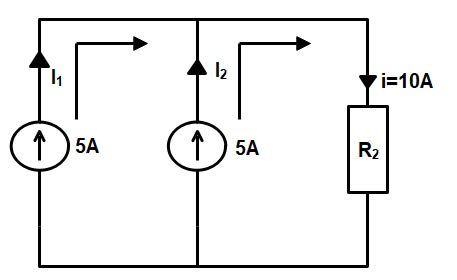
Ques.9. The circuit given below can be reduced to a single voltage source of if the Load resistance R2 = 1 ohm?
- 15 V in series with R2
- 5 V in series with R2
- 10 V in series with R2✓
- 15 V in series with R2
From the given figure the total current passing through the resistance R2 i.e 1 Ω is 10 A hence the voltage V V = R × I = 1 × 10 = 10 V Hence the voltage across the Resister R2 = 10 V so the above circuit can be reduced to a single source by connecting a voltage of 10 V and resistance of 1 Ω in series with each other as shown in the figure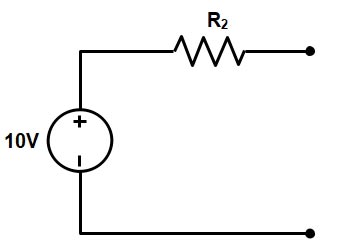
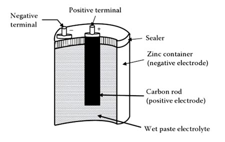
Ques.10. The voltage supplied by the zinc-electrolyte cell shown in the figure below is _______
- Approximately 0.5 V
- Approximately 1.11 V
- Approximately 1.5 V✓
- Approximately 1.74 V
A simple cell consists of two strips, or electrodes, placed in a container that holds the electrolyte. A battery is formed when two or more cells are connected. The electrodes are the conductors by which the current leaves or returns to the electrolyte. In the simple cell described above, they are carbon and zinc strips placed in the electrolyte. Zinc contains an abundance of negatively charged atoms, and carbon has an abundance of positively charged atoms. When the plates of these materials are immersed in an electrolyte, chemical action between the two begins. In a dry cell, the electrodes are the carbon rod in the center and the zinc container in which the cell is assembled. The electrolyte is the solution that acts upon the electrodes that are placed in it. The electrolyte may be a salt, an acid, or an alkaline solution. In the simple voltaic cell and in the automobile storage battery, the electrolyte is in a liquid form; in the dry cell (see Figure 10.15), the electrolyte is a moist paste. A battery consists of two or more cells placed in a common container. The cells are connected in series, in parallel, or in some combination of series and parallel, depending on the amount of voltage and current required of the battery. BATTERY OPERATION The chemical reaction within a battery provides the voltage This occurs when a conductor is connected externally to the electrodes of a cell, causing electrons to flow under the influence of a difference in potential across the electrodes from the zinc (negative) through the external conductor to the carbon (positive), returning within the solution to the zinc. After a short period, the zinc will begin to waste away because of the acid. The voltage across the electrodes depends on the materials from which the electrodes are made and the composition of the solution. The difference of potential between the carbon and zinc electrodes in a dilute solution of sulfuric acid and water is about 1.5 volts. The current that a primary cell may deliver depends on the resistance of the entire circuit, including that of the cell itself The internal resistance of the primary cell depends on the size of the electrodes, the distance between them in the solution, and the resistance of the solution. The larger the electrode and the closer together they are in solution (without touching the lower the internal resistance of the primary cell and the more current it is capable of supplying to the load. Note: When current flows through a cell, the zinc gradually dissolves in the solution and the acid is neutralized.