
Ques.21. Airblast circuit breaker is used for
- Overcurrents
- Short duty
- Intermittent duty
- Repeated duty
Answer.4. Repeated duty Explanation:- Airblast circuit breaker:- In this type of circuit breaker, compressed air is used for the arc extinction. Hence it is called a compressed air circuit breaker. Those types of circuit breakers were employed in earlier days in indoor services for voltages ranging from 11 to 1100 kV with breaking capacities up to 25000 MVA. At high voltages, this type of circuit breaker is most suitable. In the modern-day, the air blast circuit breaker is also employed in high voltage circuits in the outdoor switchyard. The air blast circuit breakers are preferred for arc furnace duty and traction systems because they are suitable for repeated duty. These type of circuit breakers are finding their best application in systems operating in the range of 132 kV to 400 kV with breaking capacities up to 7000 MVA. Advantages:- Applications The air blast circuit breakers are preferred for arc furnace duty and traction systems because they are suitable for repeated duty. These type of circuit breakers are finding their best application in systems operating in the range of 132 kV to 400 kV with breaking capacities upto 7000 MVA.
Ques.22. An efficient and well designed protective relaying should have
- Good selectivity and reliability
- Economy and simplicity
- High speed and selectivity
- All of the above
Answer.4. All of the above Explanation:- A basic requirement of a protective system is to clear the fault with sufficient speed to minimize the adverse effects of the fault. To fulfill this requirement, a protective system is required to possess the following properties. Selectivity:- Selectivity is the ability of a protective system to isolate only a faulty section of a system from the rest of the healthy power system. Selectivity is absolute if the protective scheme responds only to faults within its own zone. Whereas it is said to be relative if it is obtained by grading the settings of protective relays of different zones, all of them respond to a given fault. The absolutely selective protective systems are known as unit systems; whereas the protection systems in which selectivity is relative are known as non-unit systems. For example, differential protection is said to be a unit protective system; whereas current time graded overcurrent protection or distance protection are said to be non-unit protective systems. Reliability:- Reliability is the ability of a protective system to work properly during the period for which it is in service. The term reliability includes both the security in fault clearance and the security against undesired clearances. Quantitative reliability can be expressed as an inverse of the probability of failure. Hence, it can be said that, the less the probability of failure, the better the reliability. Failure is confined not only to protective relays but also due to breaker defects, opened control circuits, or an unfaithful transformation of inputs by system transducers, etc. Hence, each and every component of a protective system must be regarded as a potential source of failure. Speed of operation:- Speed refers to the total fault clearing time of a protective system including the protective relay tripping time as well as time taken by the breaker to open and to extinguish the arc produced between its contacts. It is obvious that the faster the speed of operation of the elements of a protective system (relay and breakers), the lesser is the damage to the power system components. This also limits the ionization at the fault, increases the chances of a successful auto-reclosing and reduces the dead time interval of a power system. Moreover, quick disconnection of the faulty section for rest of the healthy system helps in maintaining the stability of the power system. Discrimination:- A protection system should be able to discriminate between the faulty condition and the normal loading conditions, particularly, when the minimum fault current is less than the maximum load current. As for example, while protecting a power transformer, the protective system must be able to distinguish between a fault and a magnetizing inrush. Stability:- The term stability is often used to describe the quality of a protective system by virtue of which it remains inoperative under all conditions associated with faults outside its own tripping zone. In other words, it can be said that the protective system should remain stable against any type of disturbance present at any point of the power system except for an in-zone electrical fault. Sensitivity:- Sensitivity is the ability of a protective relay to react correctly to the relatively low values of fault current. Sensitivity also refers to the minimum level of fault current at which a protective relay operates. As for example, high resistance ground faults are very common for EHV and UHV transmission lines; and the protective system must be able to detect such faults before they develop further serious problems. In other words, it is the protective relay setting, usually expressed in terms of the operating quantity.Requirements for Protection System
Ques.23. The burden of a protective relay is the power
- Required to operate the circuit breaker
- Absorbed by the circuit of relay
- Developed by the relay circuit
- None of the above
Answer.2. Absorbed by the circuit of relay Explanation:- Burden:- The burden indicates the power consumption of the relay circuit elements. The power absorbed by the circuits of the relays is expressed in volt-amperes if alternating current (a.c.) and in watts if direct current (d.c.), at the rated current or voltage.
Ques.24. Directional relays are based on the flow of
- Power
- Current
- Voltage Wave
- None of the above
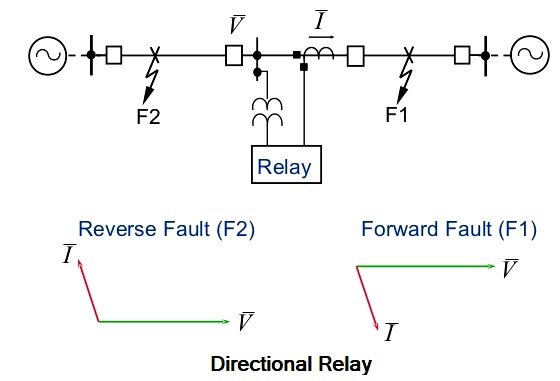
Answer.1. Power Explanation:- Wherever power flows in both directions, for example, in the present-day grid system having sources normally at both ends of the transmission line, directional relays are needed. The directional relay is connected in series with the Overcurrent relay so that the trip command is only given if there is a fault and also flow of power due to the fault in the forward direction, i.e. away from the bus. The directional relay is supplied with the current as well as the voltage. The directional feature can be achieved by comparing the direction of current flow in the line with reference to the bus voltage. In other words, the directional relay measures the phase angle between voltage and current vectors. This is why the directional relay is a two-quantity relay and a phase comparator relay, i.e., voltage and current both are fed to this relay. Therefore, the test set for the directional relay has current and voltage outputs with a facility to adjust and measure: – The relay should operate only for the direction in which it has been set to operate and over a certain phase angle zone or range which is measured (within 0 to 360°). If the phase angle is out of this zone then the relay should not operate. Directional relays can respond to positive sequence, negative sequence, or zero sequence inputs. This should be a consideration when applying directional relays at locations where zero-sequence voltage is minimal.Directional Relay
Ques.25. A differential relay measures the vector difference between
- Two current
- Two voltage
- Two similar quantities
- Any of the above
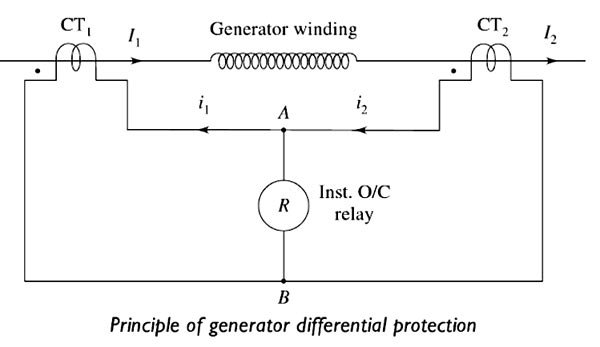
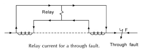
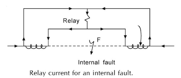
Answer.4. Any of the above Explanation:- A differential relay is defined as the relay that operates when the phasor difference of two or more similar electrical quantities exceeds a predetermined value. Thus a current differential relay operates on the result of comparison between the phase angle and magnitudes of the currents entering and leaving the Dyson to be protected. Under normal conditions, the two currents are equal in-phase and magnitude hence relay is inoperative. But under fault conditions, this condition no longer exists. The relay is connected in such a manner that the difference between current entering and current leaving flows through the operating coil. If this difference current exceeds a preset value then the relay operates and opens the circuit breaker. The simplest example of such an arrangement is shown in Figure. The system element being protected might be a part of a circuit, a winding of a generator or a transformer or a portion of a bus, etc. A current transformer is shown on each side of the protected zone. The secondary of the CTs are interconnected and an over-current relay coil is connected across the CT secondary circuit. For any fault outside the zone (a through fault) and if the two CTs having same ratios are connected properly, their secondary currents will merely circulate between the two CTs as shown in Figure. No current will flow through the relay coil and thus, it will not operate. But should a fault take place anywhere between the CTs, the phasor sum of the CT secondary currents will flow through the differential relay coil which will operate. The differential current flows whenever the current entering into the zone is not equal to the current leaving the zone. This is shown in Figure. The CT ratios may change when a large fault current flows through the primary windings. This is because of the saturation of the CT cores under such conditions. The change may not be the same for both CTs. Hence, even for a through the fault, there may be a difference in the two secondary currents and the relay may operate. The best way to get rid of this problem is by biasing the relay. The bias is obtained by circulating them through fault secondary current through an additional winding which provides a restraining force against the movement of the moving part of the relay.Differential Relay
Ques.26. A transmission line is protected by
- Time graded and current graded overcurrent protection
- Distance Protection
- Both 1 and 2
- None of the above
Answer.3. Both 1 and 2 Explanation:- The probability of faults occurring on the transmission lines is much more due to their greater length and exposure to atmospheric conditions. The main requirements of feeder protection are: (a) In the event of the fault or short circuit, the breaker close to the fault should open and all other breakers are to remain in the closed position, except in the case of grid lines. (a) in case the nearest breaker to the fault fails to open, backup protection should be provided by the adjacent breakers. (c) The relay operating time should be as short as possible in order to preserve system stability. The protection of feeders has quite a different problem, compared to the protection of generators, transformers, etc. Though differential protection is an ideal method for feeders, it is much more expensive to use, especially when the line is long. Therefore, this ideal method is not used normally, unless the line is short and needs such a high degree of Protection. Types of Protection Non-unit type (no pilot-wires)Transmission line protection
Ques.27. Large internal faults are protected by
- Merz price percentage differential protection
- Mho and ohm relays
- Horn gaps and temperature relays
- Earth fault and positive sequence relays
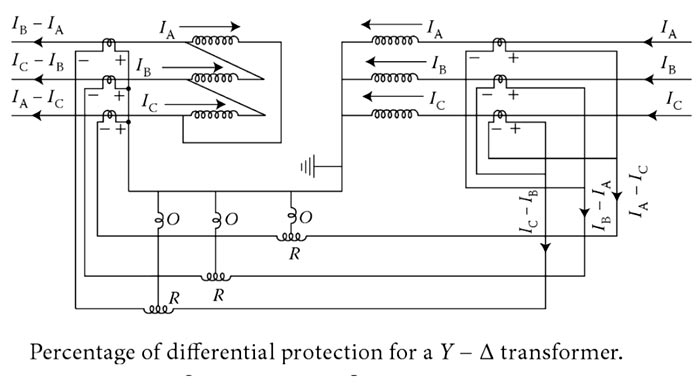
Answer.1. Merz price percentage differential protection Explanation:- This protection is also known as circulating current protection or Merz Price protection. It is used especially for short circuits within the transformer of rating 5 MVA or above. This scheme is employed for the protection of transformers against large internal short circuits. It is not capable of detecting incipient faults. The figure shows the schematic diagram of percentage differential protection for a Y- Δ transformer. The current entering end has been marked as positive. The end at which current is leaving has been marked negative. O and R are the operating and restraining coils of the relay, respectively. The connection is made in such a way that under normal conditions or in case of external faults, the current flowing in the relay operating coil due to CTs of the primary side. Consequently, the relay does not operate under such conditions. If a fault Earth fault or short circuits occur on the winding the polarity of the induced voltage of the CT of the secondary side is reversed. Now the current in the operating coil from CTs of both sides is in the same direction and causes the operation of the relay. In the star side of the transformer, CTs are connected in delta or vice versa.Percentage Differential Protection
Ques.28. When a transmission line is energized, the wave that propagates on it is?
- Current wave only
- Voltage wave only
- Both 1 and 2
- Power factor wave only
Answer.3. Both 1 and 2
Explanation:-
When a single-circuit transmission line is connected to a voltage source at t = 0, the whole length of the line is not energized all at once; there must be a time lag before the disturbance initiated at one point can be observed at the distant point in the line.
This is due to the presence of distributed constants (inductance and capacitance in a loss-free line). The process is equivalent to launching a voltage wave, which travels along the length of the line at a certain velocity (almost equal to the velocity of light) and reaches the distant end after a period of time.
The voltage wave is usually accompanied by a current wave. These two waves, which are related to each other by the characteristic impedance or resistance of the line, must reach the distant end in a finite time and, in general, must meet a discontinuity as a result of which total or partial reflection will take place.
Then, for a finite line, the voltage and current at any point (including the ends) are the result of the superimposed incident and reflected waves. In this chapter, we shall study the propagation of transient voltage and current waves along the transmission lines which may be caused by switching or lightning and which may subject the electrical systems to dangerous overvoltages.
Ques.29. Protective relays are devices that detect abnormal conditions in electrical circuits by measuring
- Current during abnormal condition
- Voltage during abnormal condition
- Constantly the electrical quantities which differ during normal and abnormal conditions
- None of the above
Answer.3. Constantly the electrical quantities which differ during normal and abnormal condition Explanation:- A relay is an automatic electric device used to initiate the isolation of a part of a circuit. A relay (automatic device) used for the protection of a circuit during abnormal conditions is called a protective relay. Protective relays require reasonably accurate reproduction of the normal and abnormal conditions in the power system for correct sensing and operation.
Ques.30. The voltage appearing across the contacts after the opening of the circuit breaker is called ______ voltage.
- Recovery
- Surge
- Operating
- Arc
Answer.1. Recovery Explanation:- Recovery Voltage Initially, this voltage is a result of the transient response of the system formed by the breaker contacts and the L-C parameters of the power system. The voltage which appears across the circuit breaker contacts immediately after the arc interruption at current zero is called the recovery voltage. or Power frequency RMS voltage, which appears across the circuit-breaker contacts after the transient oscillations die out and final extinction of arc has resulted in all the poles, is known as Recovery Voltage. Instantaneous recovery voltage at the instant of arc extinction is known as Active Recovery Voltage.
