
Ques.41. The delay fuses are used for the protection of _____
- Motors
- Power outlet circuit
- Fluorescent lamps
- Light circuits
Answer.1. Motors Explanation:- Time delay fuse:- The time delay fuse is constructed with two different types of Fusible elements overload and short circuit. These elements are somewhat similar in operation to the thermal and magnetic elements of an inverse time circuit breaker. The overload element will interrupt all overload currents, and the short-circuit element will open in response to short-circuit currents The time delay fuse can be applied in circuits subject to normal overloads and current surges (e g., motors, transformers, solenoids, etc.) without nuisance opening. Significant oversizing is not necessary.
Ques.42. Which of the following is the least expensive protection for overcurrent is a low voltage system?
- Rewireable fuse
- Isolator
- Oil circuit breaker
- Air break circuit breaker
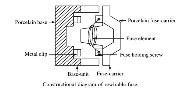
Answer.1. Rewireable fuse Explanation:- A fuse is a device, which protects the electrical wires, cables, and other electrical equipment against overloading and short circuit. It contains a fuse element, generally thin wire or strips mounted on an insulated base. It is heated and destroyed while passing an excessive current through it. It breaks the circuit by melting the fuse element when the current flowing in the circuit exceeds a certain predetermined value. The fuse is placed in series with the equipment or its parts which are to be protected. Types of Fuses They are of the following two types: Rewirable fuse In the case of a rewirable fuse, the blown-out fuse element can be replaced by a new element. The fuse element can be either open or semi-enclosed. An open type is rarely used. Semi-enclosed type is generally used for low-voltage applications in houses and installations for up to 440 V. This is the cheapest and simplest form of protection. A rewirable fuse is a set of two units. One is known as the base unit and the other is known as the fuse carrier. Fuse elements can be fixed, removed, and refixed in the fuse carrier. Fuse-carrier is also known as removable Unit. The base unit is the permanently fixed unit with the switchboard. Both the units are fixed on the porcelain chassis. The incoming wire is connected with the metal clip on one side of the porcelain base. The outgoing wire is connected with the other terminal of the porcelain base. These two terminals situated inside the base of the fuse carrier are interconnected by fuse wire. This fuse wire is the weakest part of the circuit which melts during overloading or short circuit. After that, a new fuse wire is connected between the terminals. A constructional diagram of the rewirable fuse is shown in Figure. Advantages of rewireable fuses: Disadvantages of rewireable fuse:
Ques.43. Resistance grounding is used for voltage between
- 33kV to 66kV
- 2.2 kV to 33 kV
- 3.3 kV to 11 kV
- All of the above
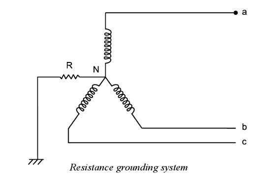
Answer.2. 2.2 kV to 33 kV Explanation:- Grounded Systems A grounded system is defined as a system of conductors in which at least one conductor, usually the system neutral, is intentionally grounded, either solidly or through a resistor or other current-limiting device. Both solid and resistance grounding can limit transient overvoltage to a safe level (250% of normal voltage); therefore, other system parameters determine the choice. The various methods of grounding the neutral of the system are: When it becomes necessary to limit the high earth-fault current, a current-limiting device is introduced between neutral and earth. As shown in Fig, a pure resistance is introduced in the neutral and the earth as the current-limiting device. The value of the resistance commonly used is quite high as compared with the system reactance. The resistor may comprise of a metallic resistance unit or a liquid resistor. It is more usual to use liquid resistors if the voltage is 6.6 kV or more. With the increase in operating voltage, the value of resistance required for grounding also increases to limit the short-circuit current during line-to-ground faults. Resistance grounding reduces the arcing-ground hazards and permits ready relaying of ground faults. This system can be operated for obtaining voltage characteristics similar to that of the isolated, earthed system. This type of resistance earthing is commonly employed for the system operating at voltages between 2.2 kV and 33 kV and the power source capacity exceeds 5,000 kVA. The advantages of resistance grounding: Disadvantages of resistance grounding:
Resistance Grounding
Ques.44. The current zero interruption, in oil and air blast circuit breaker, is achieved by
- Deionizing the oil with forced air
- Lengthening of the gap or cooling the blast effect
- Lengthening of the gap
- Cooling of the blast effect
Answer.2. Lengthening of the gap or cooling the blast effect Explanation:- Oil circuit breakers are the oldest type of circuit breakers that used oil as a dielectric or insulating medium for arc extinction. In the oil circuit breaker, the contacts of the breaker are made to separate within an insulating oil which has better insulating properties than air. Oil circuit breaker utilizes dielectric oil (transformer oil) for arc extinction. These circuit breakers can be employed for a voltage range of 33 kV to 22o kV and a breaking capacity of 1500 MVA to 7500 MVA Airblast circuit breaker:- In this type of circuit breaker, compressed air is used for the arc extinction. Hence it is called a compressed air circuit breaker. Those types of circuit breakers were employed in earlier days in indoor services for voltages ranging from 11 to 1100 kV with breaking capacities up to 25000 MVA. At high voltages, this type of circuit breaker is most suitable. In the modern-day, the air blast circuit breaker is also employed in high voltage circuits in the outdoor switchyard. The air blast circuit breakers are preferred for arc furnace duty and traction systems because they are suitable for repeated duty. These type of circuit breakers are finding their best application in systems operating in the range of 132 kV to 400 kV with breaking capacities up to 7000 MVA. After the occurrence of the fault, when the contacts of the CB begin to separate an arc is established in the contact gap. The two main causes responsible for generating an arc between the contacts of a CB are as follows: Potential difference (PD) between the contacts: When the contacts have a small separation, the PD between them is sufficient to maintain the arc. One way to extinguish the arc is to separate the contacts to such a distance that PD becomes inadequate to maintain the arc. However, this method is impracticable in a high voltage system where separation of many meters may be required. Ionized particles between contacts: The ionized particles between the contacts tend to maintain the arc. If the arc path is deionized, the arc extinction will be facilitated. This may be achieved by cooling the arc or by bodily removing the ionized particles from the space between the contacts. Methods of Arc Extinction There are two methods of extinguishing the arc in CB viz. In this method, arc resistance is made to increase with time so that current is reduced to a value insufficient to maintain the arc. Consequently, the current is interrupted or the arc is extinguished. The principal disadvantage of this method is that enormous energy is dissipated in the arc. Therefore, it is employed only in DC CBs and low-capacity AC CBs. The resistance of the arc may be increased by: Low Resistance or Current Zero Method This method is employed for arc extinction in AC circuits only. In this method, arc resistance is kept low until the current is zero where the arc extinguishes naturally and is prevented from restriking in spite of the rising voltage across the contacts. All modern high-power AC CB employ this method for arc extinction. In an AC system, the current drops to zero after every half cycle. At every current zero, the arc extinguishes for a brief moment. Now the medium between the contacts contains ions and electrons so that it has a small dielectric strength and can be easily broken down by the rising contact voltage known as restriking voltage. If such a breakdown does occur, the arc will persist for another half cycle. If immediately after current zero, the dielectric strength of the medium between contacts is built up more rapidly than the voltage across the contacts, the arc fails to restrike and the current will be interrupted. The rapid increase of dielectric strength of the medium near current zero can be achieved by
Ques.45. In Railway applications ______ circuit breaker is used.
- SFe
- Bulk oil
- Minimum oil
- Air Blast
Answer.4. Air Blast
Explanation:-
Air Blast Circuit Breaker
Air circuit breakers are normally only used at low voltage levels but are available with high current ratings up to 6,000 A and short circuit ratings up to 100 kA at 500 V. The physical size of such units, which contain large arc chutes, quickly makes them uneconomic as voltages increase above 3.6 kV.
The air-break circuit breakers are available in the range of 415 volts to 11 kV rating, the rated continuous current ranging from 100 to 4000 A and breaking current capacity up to 80000 A. As the name suggests, the insulation between the two contacts in air at normal temperature and pressure. The operating mechanism can be pneumatic, solenoid-operated or spring-operated. In the case of a spring-operated mechanism, the spring is to be charged by an induction motor (motor-operated spring mechanism). The performance and cost of the breaker are mainly decided by its breaking capacity. While breaking the fault currents, large electrodynamics forces are produced, not only due to high current but also due to the asymmetry of the fault current.
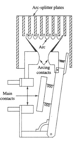
Application:- AC air-break circuit breakers are available in the voltage range 400 to 12 kV. They are widely used in low and medium-voltage systems. They are extensively used with electric furnaces, with large motors requiring frequent starting, in a place where chances of fire hazard exist, etc. Air-break circuit breakers are also used in dc circuits unto 12kV.
The air b circuit breakers are preferred for arc furnace duty and traction systems because they are suitable for repeated duty. These type of circuit breakers are finding their best application in systems operating in the range of 132 kV to 400 kV with breaker capacities upto 7000 MVA.
Ques.46. MCB protects a circuit from
- Short circuit
- Over Load only
- Both short circuit and overload
- None of the above
Answer.3. Both short circuit and overload Explanation:- Miniature Circuit breaker (MCB) This is an electro-mechanical device that breaks (that is, opens) the circuit when the current in it exceeds a given value. Unlike fuses, which melt at 50% to 100% overload, MCBs break the circuit at just 5% to 15% overload and thus provide better safety. Note that an MCB protects the circuit against both overloads and short-circuit. An MCB incorporates a thermal and magnetic tripping device. The load current flows through the thermal and electromagnetic mechanisms. In normal operation, the current is insufficient to operate either device, but when an overload occurs, the bimetal strip heats up, bends and trips the mechanism. The bimetallic strip is made up of copper and iron pasted together. A bimetallic strip is used to convert a temperature change into mechanical displacement. The time taken for this action to occur provides an MCB with the ability to discriminate between an overload that persists for a very short time, for example, the starting current of a motor, and an overload due to a fault. The device only trips when a fault current occurs. This slow operating time is ideal for overloads but when a short circuit occurs it is important to break the faulty circuit very quickly. This is achieved by the coil electromagnetic device. (b) To prevent high short-circuit current from damaging circuit elements, the MCB is also provided with a magnetic coil and plunger (known as the solenoid ). At normal operating conditions, the electromagnet is not strong enough to release the contact. When the short circuit occurs in the circuit, the current energizes the solenoid which attracts the plunger which strikes the trip lever which immediately releases the latch mechanism to open the contacts. The instantaneous opening of contacts is achieved due to the rapid operation of the solenoid.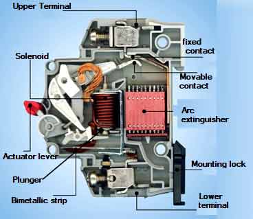
Ques.47. Wave trap is used to trap waves of
- Power frequencies
- Higher frequencies entering generator or transformer units
- Lower frequencies entering generator or transformer units
- Medium frequencies entering generator or transformer units
Answer.2. Higher frequencies entering generator or transformer units Explanation:- Wave trap is a parallel tuned inductor-capacitor tank circuit made to be resonant at desired communication frequency. The parallel tuned wave trap is connected in series with the load and is tuned to resonate at the unwanted frequency, so it presents a high impedance to this current component. A wave trap is a device that allows only a particular frequency to pass through it that it filters the signals coming on to it. So a wave trap is connected between buses and the transmission line which allows only 50 Hz signal to pass through it. Since the power transmission lines physically go between substations themselves, it is possible to use this metallic link as a communications line also. The figure shows a line between substations with a wave trap at each end. The wave trap is nothing more than a parallel tuned inductor-capacitor “tank” circuit made to be resonant at the desired communication frequency. A coupling capacitor installed on the line side of each wave trap allows the communications signal to be superimposed onto the power conductor. If the frequency of the communications signal is 250 kilohertz (kHz), the tuned wave traps on each end will effectively block the signal from passing through them onto the substation bus and into transformers and other transmission lines. Several lines between substations can have the frequency of their own communications and therefore do not interfere with each other. The impedance of the parallel tank circuit is almost nil at the power line frequency of 50 Hz and, therefore, very little power loss is experienced in the wave trap. On the other hand, the impedance of the coupling capacitor at 50 Hz is very high, so the power frequency current does not cause a phase-to-ground fault. At the same time, the impedance of the coupling capacitor at the communications frequency (250 kHz in this example) is very low; therefore, it does not take a very powerful transmitter to place the signal on the overhead power conductor. Wave traps are used to prevent carrier current from entering the power equipment in the sub-station. The wave trap also reduces cross-talk with other PLC circuits connected to the same station. One disadvantage of power line carrier applications is that a fault inside the protected zone may also short-circuit the communications channel. If a communications channel itself becomes faulted, the impedance relays may operate incorrectly during a fault or even operate when there is not a fault.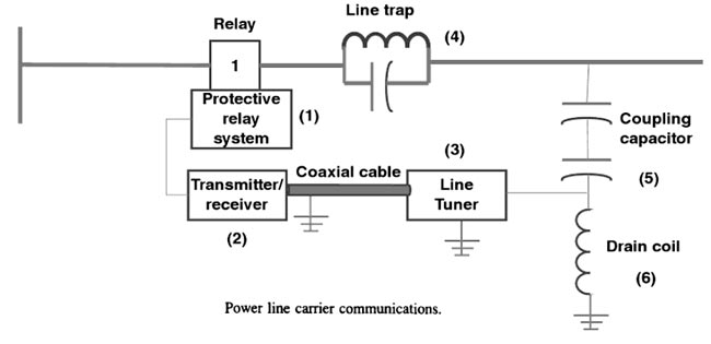
Ques.48. The underground neutral transmission system is not recommended because of the system
- Insulation being overstressed due to overvoltages
- Insulation overstress may lead to failure and subsequent phase to phase faults
- Being inadequately protected against ground fault
- All of the above
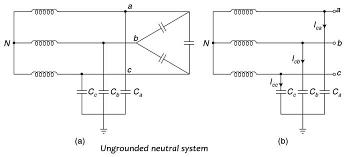
Answer.4. All of the above Explanation:- Grounding:- In a power system, the term ‘grounding’ or ‘earthing’ means electrically connecting the neutrals of the system I.e., the neutral points of star-connected 3-phase windings of power transformers, generators, motors, earthing transformers, etc.) or non-current carrying metallic parts of the electrical equipment to the general mass of earth (ground). Since the large majority of faults in the power system involve ground, power system grounding has a significant effect on the protection of all the components of the power system. Hence power system grounding is very important. Ungrounded System This is a power system without an intentional connection to the ground. However, it is connected to the ground through the natural shunt capacitance of the system to ground. The ungrounded system is also called an isolated neutral system. In an isolated neutral system, the voltage of the neutral is not fixed and may float freely. Underbalanced system conditions, the voltage of the neutral is held at the ground due to the presence of the natural shunt capacitance of the system. The three-phase conductors have, then, the phase voltages with respect to ground. Thus, as shown in Fig, in the normal balanced system, neutral (N) equals ground (G) and hence, VaN = VaG, VbN = VbG, and VCN = VCG When a ground fault occurs on any conductor, the phase-to-neutral voltages and the phase-to-ground voltages are quite different. With a ground fault on any line conductor, the faulted line conductor assumes the voltage of ground and so, the voltage of the neutral with respect to ground attains the voltage of the conductor. This is illustrated in Fig. The neutral is thus, shifted from the ground and the two healthy lines b and c will experience the line voltage (i.e.,√3 times the phase voltage) with respect to ground. A simple ungrounded neutral system is shown in Fig. The line conductors have capacitances between one another and to the ground, the former being delta connected while the latter are star-connected. Advantages of the Ungrounded neutral system The following are the few advantages of the ungrounded (isolated) neutral system. (i) In case of a single line-to-ground fault, the fault current is very small. Hence, it is possible to maintain the supply with a fault on one line. (ii) Interference with communication lines is reduced because of the absence of zero sequence currents. Advantages of the Ungrounded neutral system (i) Under a single line-to-ground fault, the voltage of the faulty phase (line) becomes equal to the ground voltage and the voltages of the two remaining healthy phases (lines) with respect to ground rise from their normal phase to neutral voltages to full line value (i.e., √3 times the normal phase value). This causes stress on the insulation. (ii) The voltage of the neutral is not fixed and may float freely. Hence neutral is not stable. (iii) The capacitive current in the two healthy phases increases to ~ times the normal value. (iv) The capacitive fault current (If) in the faulty phase is 3 times the normal per phase capacitive current. (v) Persistent arcing ground occurs. Due to the arcing ground, the system capacitance is charged and discharged in a cyclic order. This results in high-frequency oscillations being superimposed on the whole system and the phase-voltage of healthy phases may rise to 5 to 6 times its normal value. The overvoltages may result in insulation breakdown. (vi) The ground fault protection of ungrounded systems becomes difficult because the capacitive fault current is so small in magnitude that it may not be sufficient to operate-protective devices (i.e., ground fault relays). (vii) Because of the capacitive fault current is small, there will be very little effect on the neighboring communication circuit. However, the long duration of the arc which may be as long as 30 minutes, may offset this advantage. The advantages of the ungrounded neutral system are of negligible importance as compared to their disadvantages. With the growth of power systems in terms of power transmitted, voltage level and distance of transmission, many difficulties were being encountered in ungrounded systems. Therefore, ungrounded systems are no more used. The modern power systems operate with neutral grounding at every voltage level.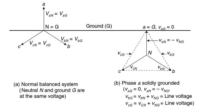
Ques.49. The reflection coefficient at the open-circuited end of a transmission line
- Zero
- Infinity
- Unity
- None of the above
Answer.3. Unity Explanation:- The ratio of the reflected wave to the incident wave is known as the reflection coefficient and is simply a measure of the quality of the match between the transmission line and the terminating impedances. In the general case, the amplitude of the wave reflected at the end of the transmission line is determined by the reflection coefficient, ρ (rho). The value of ρ depends on ZO and Zterms the termination impedance that appears at the end of the line: ρ = Reflection coefficient = (Zterms − ZO) ⁄ (Zterms + ZO) When a voltage wave with amplitude Vwave hits the end of a transmission line the wave with amplitude ρ · Vwave is reflected. Note that three simple cases match Zterms = ZO :- When a transmission line is terminated in its characteristic impedance, the reflection coefficient is 0. Zterms = 0:- The reflection coefficient of a short-circuited line is -1, producing a reflection of equal magnitude and opposite polarity. Zterms = ∞ :– The reflection coefficient of an open-circuited line is −1, producing a reflection of equal magnitude and the same Polarity.
Ques.50. For the protection of power station buildings against direct strokes the requirements are
- Interception
- Interception and conduction
- Interception, conduction, and dissipation
- Interception, conduction, dissipation, and reflection
Answer.3. Interception, conduction, and dissipation Explanation:- Protection Against Lightning Proper protection must be provided to the power stations, substations, overhead transmission lines from the direct lightning strokes while the electrical apparatus must be protected from indirect strokes in the form of travailing waves. the lightning strokes can cause more severe damage than other types of switching surges or transients. Hence protection against lightning strokes is an important consideration in the system design. Protection of Generating Stations and Substations Against Direct Strokes Generally, the generating stations are housed In big buildings while the substations are housed in switchyard or outdoor. To protect a structure against direct strokes, three requirements must be fulfilled. These involve: (a) an object in good electrical connection with the earth to attract the leader stroke. (b) a path joining this object to earth of a low impedance. (c) a low resistance connection with the earth. For INTERCEPTION OF LIGHTNING STROKE, the upper portion of a metal structure, or a separate metallic system (often called shield) mounted on the structure may be used. A particular shield configuration is in the form of masts or Overhead ground wires. This provides good shielding to the effect that out of 1000 strokes on the shield or shielded object, 999 will terminate on the shield and only one on the protected object. This is called 0.1% exposure. Such is the effect of good shielding. For CONDUCTION OF LIGHTNING CURRENT the requirements are: (i) low resistance (ii) low reactance, since in the long circuitous line the rapid rate of rise of lightning current may produce high voltage due to high inductance. (iii) Sufficient clearance from any other conducting object. For dissipation of Lightning Current suitable grounding methods must be employed such as resistance grounding.
