Switchgear and Protection Question & answer
Ques.1. The main function of a fuse is to
- Protect the line
- Open the circuit
- Prevent excessive currents
- None of the above
Answer.3. Prevent Excessive current Explanation:- Fuse is the current interrupting device that breaks or opens the circuit (in which it is inserted) by fusing the elements when the current in the circuit exceeds a certain value. Fuse is the simplest and cheapest device used for interrupting an electrical circuit under the condition of short-circuiting, or excessive overload, current magnitudes. A fuse is a safety device having a short length of a thin, tin-plated copper wire having a low melting point, which melts and breaks the circuit if the current exceeds a safe value. The thickness and length of the fuse wire depend on the maximum current allowed through the circuit. An electric fuse works on the heating effect of current. The fuse for protecting our domestic wiring is fitted just above our main switch on the switchboard. A fuse wire is connected in series in the electric circuits.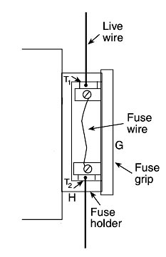
Ques.2. On which of the following routine tests are conducted?
- Oil circuit breakers
- Airblast circuit breakers
- Minimum oil circuit breakers
- All of the above
Answer.4. All of the above Explanation:- The routine tests are performed on each individual circuit breaker of proven design; the purpose is to prove the correctness of the assembly and the material used and to check the proper functioning of the Circuit Breaker. The routine tests include the following tests: (a) Operational tests. (b) Measurement of resistance of the main circuits. (c) One-minute power frequency voltage dry withstand tests. The test procedures, methods of finding results, tests to be performed, etc. are specified by Standards Organizations. It is commonly accepted and provided in various standards that the certificates of type tests shall be considered as evidence of the compliance of the circuit breakers with the relevant clauses of the specifications and the manufacturer shall make available such certificates together with the detailed drawings of the circuit breakers and a record of any alteration that may have been made in the subsequent to the type tests. Type tests can be broadly classified as: Short circuit tests are of utmost importance and will be dealt with in detail in the next section. However, a brief account of other tests is given below, (a) Mechanical tests: These are mechanical endurance type-tests involving repeated opening and closing of the breaker. The circuit breaker is opened and closed several times (500) without any current in the current-carrying parts. Some operations (50) are by energizing the relays, the remaining are by closing the trip circuit by other means. No adjustments are permissible during testing. After the test, there should be no distortion or wear of the parts. (b) Thermal tests: These are conducted by passing an alternating current of normal frequency through the current-carrying parts of the circuit breaker. The temperature is measured by thermometers or thermocouples with temperature indicators or self-resistance methods. The temperature rises for rated current should not exceed 40°C for currents less than 800 A normal current and 50°C for the normal value of current 800 A and above. (c) Dielectric tests: These are conducted for testing the insulators of the breaker. These can be classified as: Power frequency tests: Conducted on a clean new circuit breaker, the test voltage varies with a circuit breaker rated voltage. The test voltage with a frequency between 15-100 Hz is applied as follows: (i) Between poles with circuit breaker closed, (ii) Between poles and earth with circuit breaker open (iii) Across terminals with circuit breaker open. The voltage is gradually increased and maintained at the test value for 1 minute. Impulse tests: in this test impulse voltage of specified shape and magnitude is applied to the breaker. For the outdoor circuit, dry and wet tests are conducted. (d) Short-circuit test: These are conducted in short-circuit testing stations and are mainly meant to prove the ratings of the circuit breaker. Before discussing the tests properly, it would be worthwhile to discuss the short-circuit testing stations.Routine Tests
Ques.3. SF6 gas
- Is yellow in color
- Is lighter than air
- Is nontoxic
- Has pungent small
Answer.3. Is nontoxic Explanation:- The different types of high voltage circuit breakers include the following SF6 gas circuit breakers are widely used for EHV applications today, as Sulphur hexafluoride(SF6) gas is an electronegative gas having excellent dielectric and arc quenching properties resulting in many advantages such as compactness and less maintenance of EHV circuit breaker Circuit breakers are mechanical device designed to close or open contacts members, thus closing or opening of an electrical circuit under normal or abnormal conditions. Circuit breakers are made in varying sizes, from small devices that protect low-current circuits or individual household appliances, up to large switchgear designed to protect high voltage circuits feeding an entire city. The properties of SF6 gas are divided as Physical Properties Chemical Properties Dielectric PropertiesTypes of Circuit Breakers
Properties of SF6 Gas
Ques.4. The arcing contacts in a circuit breaker are made of
- Copper tungsten alloy
- Porcelain
- Electrolytic copper
- Aluminum alloy
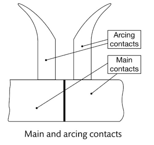
Answer.1. Copper tungsten alloy Explanation:- The assembly of the fixed and moving contacts along with other parts of the ‘current-carrying circuit’ form a very important portion of any switchgear. Every part of the conducting circuit should be designed to carry the required current and withstand the consequential electrodynamic forces. It comprises all or some of the following components/parts. Main Contacts They carry the load currents and the let-through overcurrents. They are bulky and made of pure copper with a thick silver coating. Their mating surfaces are slightly ‘roughened’ to ensure better ‘contact’, i.e., ‘lower contact resistance’. Sometimes, the ‘silver button’ is brazed to the ‘main copper body’ of the contact so that the ‘button’ forms the mating surface. Arcing Contacts The switchgear may or may not have arcing contacts separated from the main contacts. However, when provided, they exist on both fixed and moving contact sets. They are ‘open’ during the normal operation of switchgear in ‘closed’ status and carry no currents. They are shaped and assembled in such a way that their movement is as described below. (a) During the closing operation, the arcing contacts touch each other at first, then the main contacts touch and the arcing contacts part. (b) During the opening operation, the arcing contacts touch first, the main contacts separate, and thereafter the arcing contacts separate. With this arrangement, the arc is always struck between the arcing contacts only. They are designed to be light (to assist faster movements) and made to be inexpensive since they generally need to be replaced after every two or three current interruptions. Fig. shows the typical shapes and the relative ‘positioning’ of main and arcing contacts. The main contacts carry the normal current without giving a high millivolt drop, and the contacts must be made with enough pressure because there could be an opening tendency even when the rated current is canned by the breaker, particularly for breakers with higher current ratings. The main contacts are made of copper-cadmium alloys. The arcing contacts are made up of heat-resistant material like copper tungsten, or silver tungsten.Conducting Circuit
Ques.5. Which of the following medium is employed for the extinction of arc in air circuit breaker?
- Water
- Oil
- Air
- SF6
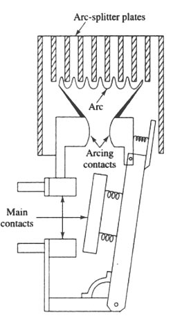
Answer.3. Air Explanation:- Air circuit breakers are normally only used at low voltage levels but are available with high current ratings up to 6,000 A and short circuit ratings up to 100 kA at 500 V. The physical size of such units, which contain large arc chutes, quickly makes them uneconomic as voltages increase above 3.6 kV. The air-break circuit breakers are available in the range of 415 volts to 11 kV rating, the rated continuous current ranging from 100 to 4000 A and breaking current capacity up to 80000 A. As the name suggests, the insulation between the two contacts in air at normal temperature and pressure. The operating mechanism can be pneumatic, solenoid-operated, or spring-operated. In the case of a spring-operated mechanism, the spring is to be charged by an induction motor (motor-operated spring mechanism). The performance and cost of the breaker are mainly decided by its breaking capacity. While breaking the fault currents, large electrodynamics forces are produced, not only due to high current but also due to the asymmetry of the fault current. These electrodynamics forces act on the operating mechanism and because of these forces, there is a tendency for contact opening. This may deteriorate the contact surfaces. Immediately after the fault current is interrupted large high-frequency voltage transients are produced across the contacts. Both of these, high voltage and high currents decide the breaking capacity (i.e., the capacity of the breaker to deal with high currents without being damaged).Air Break Circuit Breaker or Air Blast Circuit Breaker
Ques.6. With which of the following, a circuit breaker must be equipped for remote operation?
- Inverse time trip
- Time-delay trip
- Shunt trip
- All of the above
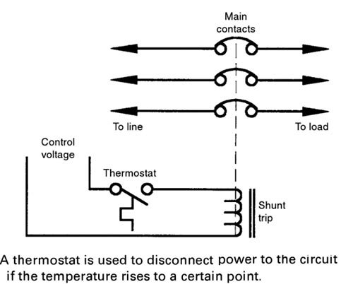
Answer.3. Shunt trip Explanation:- Some circuit breakers contain a small solenoid coil known as a shunt trip. Shunt trips are used to open the circuit breaker contacts by energizing the solenoid from an external source. Assume, for example, that it is desirable to disconnect the power to a circuit if the temperature rises above a certain level. If the circuit breaker protecting the circuit contains a shunt trip, a thermostat can be connected in series with the solenoid. If the temperature rises above the desired level, the thermostat contacts will close and energize the coil, Figure. When the coil energizes, the circuit-breaker contacts will open and disconnect power to the circuit. A shunt trip relay completes the circuit between the control-power source and the solenoid coil. Shunt trips are used to trip a circuit breaker electrically from a remote location and consist of a momentary-rated solenoid tripping device mounted inside a molded case. The shunt trip can remotely trip the breaker but cannot remotely reclose the breaker. To recluse the breaker, the breaker handle must first be moved to the reset position and then to the “on” position.Shunt Trips
Ques.7. A protective device, which reduces the steepness of wavefront of a surge by absorbing surge energy is called
- Surge Diverters
- Surge absorber
- Switching surges
- Earthing screen
Answer.2. Surge absorber Explanation:- Surge Absorber The steepness of the wavefront of travailing waves can cause damage to the apparatus in addition to the magnitude of the wave. The steeper is the traveling wave, the more damage to the apparatus is more. Thus to reduce the steepness of the wavefront of the surge, a surge absorber is used. The surge absorber is a protective device that can reduce the steepness of the wavefront of a surge and absorbs energy contained in travailing waves. Though the surge diverter and surge absorber eliminate the surge, the way in which it is done is different in the two devices. The surge diverter diverts the surge to the earth while the surge absorber absorbs energy contained in the surge. The capacitor is used as a surge absorber. XC = 1/2πfC, for high frequency, it offers low reactance. A surge is a high-frequency wave, the capacitor acts as a short circuit device, passing it to earth. In another type of surge absorber, the parallel combination of resistor and inductor is used as a surge absorber. This combination is placed in series with the line steep wavefronts. Since XL = 2πfL, the inductor offers high resistance at high frequencies. The surge then flows through the resistor, where it is dissipated.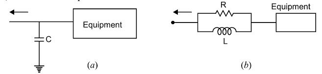
Ques.8. A thermal protection switch can protect against
- Short-circuit
- Temperature
- Overload
- Overvoltage
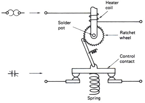
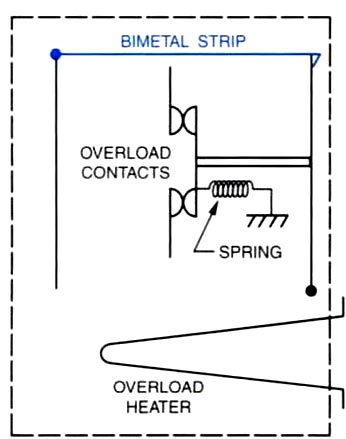
Answer.3. Overload Explanation:- The thermal protection switch protects against overload. Thermal overload relay or switches can be divided into two types:- Melting overload Relay or Solder Melting Pot To create this type of overload, a bra shaft is placed inside a brass tube. In these overload relays (also referred to as “solder pot relays”), the motor current passes through a small heater winding. The heating element is connected in series with the motor. The current that flows through the motor windings also flows through the heating element. The heating element is calibrated to produce a certain amount of heat when a predetermined amount of current flows through it. As long as the current flowing through it does not exceed a certain amount, there is not enough heat produced to melt the solder. Under overload conditions, an excessive amount of current will flow through the heater causing excessive heat the heat causes a special solder to melt, allowing a ratchet wheel to spin free, opening the contacts. When this occurs, the relay is said to ” trip.” To obtain appropriate tripping current for motors of different sizes, of different full-load currents, a range of thermal units (heaters) is available. The heater coil and solder pot are combined in a one-piece, non-tamperable unit. The heat transfer characteristic and the accuracy of the unit cannot be accidentally changed, as is possible when the heater is a separate component. Melting alloy thermal overload relays are “hand reset,” thus after they trip they must be reset by a deliberate hand operation. A reset button is usually mounted on the cover of enclosed starters. Thermal units are rated in amperes and are selected on the basis of motor full-load current. Bimetal type Overload Relay The bimetal type of overload operates very similarly to the solder-melting type except a bimetal strip is used to cause the contacts to open. In this unit, the bimetal strip is used to mechanically hold the spring-loaded contacts closed. If the current flow through the heater becomes excessive the bimetal strip will warp and permit the spring to open the contacts. After the overload unit has tripped the bimetal strip must be allowed some time to cool before it can be reset. This type of unit has an advantage over the solder-melting type in that it, be adjusted for manual reset or automatic. The solder-melting type of overload must be manually reset.
Ques.9. Arc in a circuit behaves as
- A capacitive reactance
- An inductive reactance
- A resistance increasing with voltage rise across the arc
- A resistance decreasing with voltage rise across the arc
Answer.3. A resistance increasing with voltage rise across the arc Explanation:- An electric arc is a visible plasma discharge between two electrodes that is caused by electrical current ionizing gasses in the air. Electric arcs occur in nature in the form of lightning. With proper control, electric arcs can be harnessed and used industrially for welding, plasma cutting, and even certain types of lighting such as fluorescent lighting where a high voltage ionizes the inert gas within a glass tube; the flow of current across the ionized gas liberates visible light. The electric arc is a self-sustained electrical discharge that exhibits a low voltage drop, is capable of sustaining large currents, and behaves like a non-linear resistor. Though the most Commonly observed arc discharge occurs across the air at atmospheric conditions, the arc discharge is also observed at high and low pressures, in a vacuum environment, and in a variety of gases and metal vapors. As the volt-ampere characteristics of an arc voltage are negative i.e arc voltage is high when the arc current is low and vice-versa. In order to maintain the ionization of the gas, when the arc is effectively cooled, the magnitude of the arc voltage must increase. What this means is simply that as the arc cools, the cooling efficiency increases the deionization of the arc space, which in turn increases the arc resistance. As a consequence of the increase in resistance, the short circuit current and the phase angle are reduced and thus the likelihood of a successful interruption is significantly enhanced. In an air circuit breaker, increasing the resistance of the arc in effect ins creases the arc voltage. Thus, to effectively increase the arc voltage any of We following means can be used:
and the same is attributed to increasing in resistance to the flow of current due to the reduction in charged particle density in arc zones with an increase in arc length.
Ques.10. The thermal circuit breaker has
- Delayed trip action
- Instantaneous trip action
- Instantaneous short action
- Any of the above
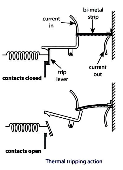
Answer.1. Delayed trip action Explanation:- This type depends upon the effect of heat on a bimetal strip for its operation. Such a strip bends on heating and, in the thermal circuit breaker, bending of the strip causes contact to open, which breaks the circuit. The bimetal strip is usually in series connection in the electrical circuit, its temperature being governed by the current flowing through it. As the current increases, the temperature of the bimetal strip rises, bending more the hotter it becomes. The load current is passed through a small heater coil wrapped around a bi-metal strip inside the MCB housing; the heat created depends on the current it carries. This heater is designed to warm the bi-metal strip either directly (the current passes through the bi-metal strip which in effect is part of the electrical circuit) or indirectly (where a coil of current-carrying conductor is wound around the bi-metal strip) and the excess current warms the bi-metal strip. The bi-metal strip is made of two different metals, normally brass and steel (brass expanding more than steel). These two dissimilar metals are securely riveted or welded together along their length. The rate of expansion of the two metals is different so that when the strip is warmed, it will bend and will trip the latch, due to its expansion coefficient, its action is time delayed. The bi-metal strips are arranged so that normal currents will not heat the strip to the tripping point. However, if current increases beyond the rated value, the heater increases in temperature, and thus the bi-metal strip is raised in temperature, trips the latch, and breaks the circuit. The thermal relay is not suitable for operation on short-circuit as it will burns the elements sufficiently before the strip may deflect so as to close the contacts.Thermal circuit breaker