100 Most Important MCQ OF Synchronous Generator or Alternator | Objective Type Question OF Alternator OR synchronous Generator with Explanation
Ques.1. The salient-pole construction for the field structure of an alternator is generally used for _______ machine.
4 pole
2 Pole
6 Pole
8 Pole
Answer.4. 8 Pole
Explanation
The salient pole rotors are driven by low-speed water turbines or diesel engines. It is because the salient-pole type construction is difficult to build to withstand the stresses at high speeds. Because a salient pole rotor turns at low speed (50 to 300 r.p.m.) and because a frequency of 50 Hz is required, we must place a large number of poles on the rotor. The speed of an alternator is given as
N = 120f/P
Hence the speed of an alternator is inversely proportional to the number of poles. As discussed above the salient pole alternator turns at low speed, therefore, the number of poles required to be more.
Ques.2. The a.c. the armature winding of an alternator is
Delta Star connected
Generally Delta Connected
Star Delta Connected
Always Star connected
Answer.4. Always Star connected
Explanation
Alternators are connected primarily in the star to achieve the following motives:
More economical:- The phase voltages in star connection are 57.7 % of the line voltages, i.e. the armature winding in star connection is less exposed to voltage as compared to the delta connection which in turn prove more economic if we consider insulation, breakdown strength, the requirement of conductor material
Availability of neutral: It is very important for an alternator to have a neutral point. This neutral point is to be grounded through a resistor, for stability purposes. The neutral allows a path for circulating currents under unbalanced loaded conditions, and also during faults. If there was no path for the flow of fault current, and a line to ground fault occurs in one of the three phases, there would be a rise in voltages in the other two healthy phases and eventually, it would cause insulation failure in the other two phases and the line to ground fault would lead to a 3 phase fault. A neutral point would avoid all this and limit the fault condition to one phase only. Insulation would be protected, and the lines can be operational after fault isolation. For all this to happen, the star connection in the stator is absolutely necessary.
Zero sequences current Path:- In star connection, if the neutral is grounded then it also provides a path for the Zero-Sequence currents during faults, whereas in the delta connection the zero sequence currents flow within the delta circuit and hence increasing the load on the winding.
Easy protection: Neutral grounding is necessary to allow zero sequence currents to flow to the ground in case of a fault.
Elimination of harmonics: Star connection facilitates a neutral connection which is instrumental in eliminating triple harmonics.
No circulating currents: In star connection, we don’t have circulating parasitic currents like in Delta which lead to heating losses.
Ques.3. Drop-in alternator frequency is corrected by:
Automatic Voltage Regulator
Damper Winding
Increase Prime Mover Output
Decrease Prime Mover Output
Answer.3. Increase Prime Mover Output
Explanation
Alternator frequency depends on two things:
The NUMBER OF POLES in the rotating field
The SPEED at which the poles rotate.
You can’t change the number of poles. That was determined when the alternator was built. However, you can change the speed. The rotating field poles are mounted on the shaft of the prime mover. Changing the speed of the prime mover will directly affect the frequency output of the alternator.
The frequency of an alternator can be adjusted by changing the speed of the Prime Mover as we know that
Ns = 120f/P
Ns ∝ f
Hence the speed of the prime mover is directly proportional to the alternator frequency therefore by changing the speed of Prime-mover we can correct the Drop-in the alternator frequency.
Ques.4. The pitch factor for a full pitch winding of a synchronous machine is
0
0.5
0.9
1
Answer.4. 1
Explanation
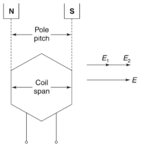
Pitch factor is the ratio between the winding pitch and pole pitch
Pitch factor = Winding pitch/Pole pitch
Pole pitch may be defined as the distance between the two adjacent poles, which is nothing but the periphery of the armature divided by the number of poles. In other words, it is the number of armature conductors or the number of armature slots per pole.
Pole Pitch between two adjacent poles in case of any machine will always be 180 degrees electrical.
In the case of full pitch winding, the winding pitch is equal to the pole pitch. For full pitch winding the pitch factor is equal to unity and the winding is known as “full pitch winding”.
Ques.5. In the case of Zero Power factor leading load on the alternator, the effect of armature reaction is
To demagnetize
To increase induced EMF
To cross -Magnetize
To decrease the Induced EMF
Answer.4. To increase induced EMF
Explanation
Armature Reaction
When the load is connected to the alternator, the armature winding of the alternator carries a current. Every current-carrying conductor produces its own flux so the armature of the alternator also produces its own flux when carrying a current. So there are two fluxes present in the air gap, one due to armature current while the second is produced by the field winding called main flux. The flux produced by the armature is called armature flux.
So the effect of the armature flux on the main flux affecting its value and the distribution called armature reaction. The effect of the armature flux not only depends on the magnitude of the current flowing through the armature winding but also depends on the nature of the power factor of the load connected to the alternator
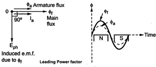
Zero Leading Power Factor Load (Magnetizing) Under-excited
Consider a purely capacitive load connected to the alternator having zero leading power factor. This means that armature current Iaph driven by Eph leads Eph by 90° which is the power factor angle φ. Induced e.m.f. Eph lags φf by 90° while Iaph and φa, are always in the same direction.
The armature flux and the main field flux are in the same direction i.e. they are helping each other. This results in the addition of the main flux. Such an effect each armature reaction due to which armature flux assists field flux is called the magnetizing effect of the armature reaction This effect adds the flux to the main flux, greater e.m.f. gets induced in the armature Hence there is an increase in the terminal voltage for leading power factor loads. For intermediate power factor loads i.e. between zero lagging and zero leading the armature reaction is partly cross magnetizing and partly demagnetizing for lagging power factor loads or partly magnetizing for leading power factor loads.
Ques.6. In the synchronous motor rotor, copper losses are met by
Armature Input
AC Input
DC source
Supply mains
Answer.3. DC Source
Explanation
The synchronous motor consist of two parts:
Stator: Stator is the armature winding. It consists of three-phase star or delta connected winding and excited by 3 phase A.C supply.
Rotor: Rotor is a field winding. The field winding is excited by the separate D.C supply through the slip ring.
The 3 phase Ac source feeds electrical power to the armature for the following component of the power
The net mechanical output from the shaft.
Copper losses in the armature winding.
Friction and the armature core losses.
The power received by the DC source is used to utilized only to meet copper losses of the field winding.
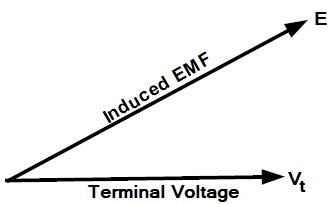
Ques.7. The phasor diagram of the synchronous machine connected to an infinite bus is shown in Figure. The machine is acting as a
Generator and operating at lagging power factor
Generator and operating at leading power factor
Motor and operating at lagging power factor
Motor and operating at leading power factor
Answer.1. Generator and operating at lagging power factor
Explanation
The voltage regulation of an alternator is defined as the change in its terminal voltage when the full load is removed, keeping field excitation and speed constant, divided by the rated terminal voltage.
So if Vph = Rated terminal voltage
Eph = No load-induced e.m.f
Regulation = (Eph -Vph)/Vph
The value of the regulation not only depends on the load current but also on the power factor of the load.
For lagging and unity p.f. conditions there is always a drop in the terminal voltage hence regulation values are always positive.
Ques.8. In the case of the leading power factor, the terminal voltage of the alternator will
Rise on adding the full Load
Rise on removing the full load
Fall on adding the full load
Fall on removing the full load
Answer.2. Rise on removing the full load
Explanation
Under the load condition, the terminal voltage of the alternator is less than the induced e.m.f(Eph). So if the load is disconnected, Vph(per phase rated terminal voltage) will change from Vph to Eph, if flux and speed are maintained constant. This is because when the load is disconnected, Ia is zero hence there are no voltage drops and no armature flux to cause armature reaction. This change in the terminal voltage is significant in defining the voltage regulation.
The voltage regulation of an alternator is defined as the change in its terminal voltage when the full load is removed, keeping field excitation and speed constant, divided by the rated terminal voltage. So if
Vph= Rated terminal voltage
Eph= No load-induced e.m.f
Regulation = (Eph -Vph)/Vph
The value of the regulation not only depends on the load current but also on the power factor of the load.
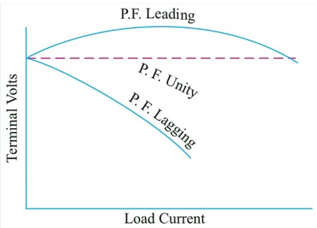
For lagging and unity p.f. conditions there is always a drop in the terminal voltage hence regulation values are always positive.
While for leading capacitive load conditions, the terminal voltage increases as load current increases. Hence the regulation is negative in such cases. Hence the terminal voltage will fall on removing the full-load.
The relationship between the load current and the terminal voltage is called the load characteristics of an alternator. Such load characteristics for various load power factor is shown in fig.
Ques.9. When any one-phase of a 3-phase synchronous motor is short-circuited, the motor
Will overheat in the spot
Will fail to pull into step
Will refuse to start
Will not come upto speed
Answer.3. Will refuse to start
Explanation
Failure of a synchronous motor to start is often due to faulty connections in the auxiliary apparatus. This should be carefully inspected for open circuits or poor connections. An open circuit in one phase of the motor itself or a short circuit will prevent the motor from starting.
Most synchronous motors are provided with an ammeter in each phase so that the last two causes can be determined from their indications: no current in one phase in case of an open circuit and excessive current in case of a short circuit. Either condition will usually be accompanied by a decided buzzing noise, and a short-circuited coil will often be quickly burned out. The effect of a short circuit is sometimes caused by two grounds on the machine.
Difficulties in starting synchronous motors:- A synchronous motor starts as an induction motor. The starting torque, as in an induction motor, is proportional to the square of the applied voltage. For example, if the voltage is halved, the starting effort is quartered. When a synchronous motor will not start, the cause may be that the voltage on the line has been pulled below the value necessary for starting. In general, at least half voltage is required to start a synchronous motor.
Difficulty in starting may also be caused by an open circuit in one of the lines to the motor. Assume the motor to be three-phase. If one of the lines is open, the motor becomes single-phase, and no single-phase synchronous motor, as such, is self-starting. The motor, therefore, will not start and will soon get hot. The same condition is true of a two-phase motor if one of the phases is open-circuited.
Difficulty in starting may be due to a rather slight increase in static friction. It may be that the bearings are too tight, perhaps from cutting during the previous run. Excessive belt tension, if the synchronous motor is belted to its load or any cause which increases starting friction will probably give trouble. Difficulty in starting may be due to field excitation on the motor. After excitation exceeds one-quarter of normal value, the starting torque is influenced. With full field on, most synchronous motors will not start at all. The field should be short-circuited through a proper resistance during the starting period.
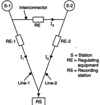
Ques.10. The angular displacement between two interconnected stations is mainly due to
Armature reactance of both alternators
Reactance of the interconnector
Synchronous reactance of both the alternators
All of the above
Answer.1. Armature reactance of both alternators
Explanation
In an interconnected station to transfer large load between the stations, it is required that the load on the line must be shared equally.
Consider the 2 generating station S-1 and S-2 supplying a Receiving station RS through line 1 and line 2.
To deliver equal power through line 1 and line 2 the phase and active component of line current I1 and I2 must be equal.
To compensate Impedance drop the regulating components (RE) are installed at the sending end of each transmission line.
The parallel operation and load sharing between two alternators are possible because of alternator internal reactance which limits the short circuit current and allows angular displacement between two stations.