
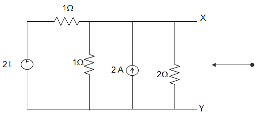
21. A circuit is given in the figure below. The Thevenin equivalent as viewed from terminals x and x’s is ___________
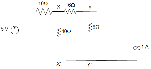
A. 8 V and 6 Ω
B. 5 V and 6 Ω
C. 5 V and 32 Ω
D. 8 V and 32 Ω
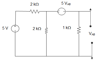
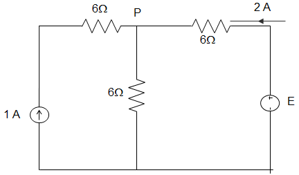
22. For the circuit given in the figure below, the Thevenin equivalent as viewed from terminals y and y’ is _________
A. 8 V and 32 Ω
B. 4 V and 32 Ω
C. 5 V and 6 Ω
D. 7 V and 6 Ω
Answer: D
We, Thevenized the left side of xx’, and the source transformed the right side of yy’.
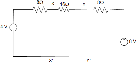
Thevenin equivalent as seen from terminal yy’ is
Vxx’ = Vth = \(\displaystyle\frac{\frac{4}{8} + \frac{8}{24}}{\frac{1}{8} + \frac{1}{24}}\) = 5V
(0.167 + 1)/(0.04167 + 0.125) = 7 V
∴ Rth = (8 + 16) || 8
= (24×8}/(24 + 8) = 6 Ω.
[/bg_collapse]
23. In the following circuit, when R = 0 Ω, the current IR equals to 10 A. The value of R, for which maximum power is absorbed by it is ___________
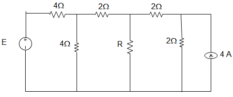
A. 4 Ω
B. 3 Ω
C. 2 Ω
D. 1 Ω
24. In the following circuit, when R = 0 Ω, the current IR equals to 10 A. The maximum power will be?
A. 50 W
B. 100 W
C. 200 W
D. 400 W
25. For the circuit given below, the Thevenin resistance across the terminals A and B is ________
A. 5 Ω
B. 7 kΩ
C. 1.5 kΩ
D. 1.1 kΩ
26. For the circuit given below, the Thevenin voltage across the terminals A and B is ____________
A. 1.25 V
B. 0.25 V
C. 1 V
D. 0.5 V
Answer: D
Current through 1 Ω = (5/2) – I1
Using source transformation to 5 V sources
VOC = 1 × I1
VOC = − 5 VOC + (5/2) – I1) × 1
Eliminating I1, we get, VOC = 0.5 V.
[/bg_collapse]
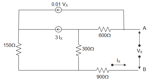
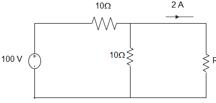
27. In the following circuit, the value of open-circuit voltage and the Thevenin resistance between terminals a and b are ________
A. VOC = 100 V, RTH = 1800 Ω
B. VOC = 0 V, RTH = 270 Ω
C. VOC = 100 V, RTH = 90 Ω
D. VOC = 0 V, RTH = 90 Ω
Answer: D
By writing loop equations for the circuit, we get,
VS = VX, IS = IX
VS = 600(I1 – I2) + 300(I1 – I2) + 900 I1
= (600 + 300 + 900) I1 – 600I2 – 300I3
= 1800I1 – 600I2 – 300I3
I1 = IS, I2 = 0.3 VS
I3 = 3IS + 0.2VS
VS = 1800IS – 600(0.01VS) – 300(3IS + 0.01VS)
= 1800IS – 6VS – 900IS – 3VS
10VS = 900IS
For Thevenin equivalent, VS = RTH IS + VOC
So, Thevenin voltage VOC = 0
Resistance RTH = 90Ω.
[/bg_collapse]
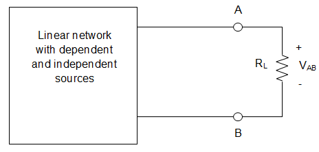
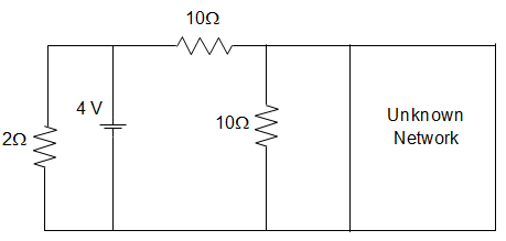
28. In the circuit given below, it is given that VAB = 4 V for RL = 10 kΩ and VAB = 1 V for RL = 2kΩ. The values of the Thevenin resistance and voltage for the network N are ____________
A. 16 kΩ and 30 V
B. 30 kΩ and 16 V
C. 3 kΩ and 6 V
D. 50 kΩ and 30 V
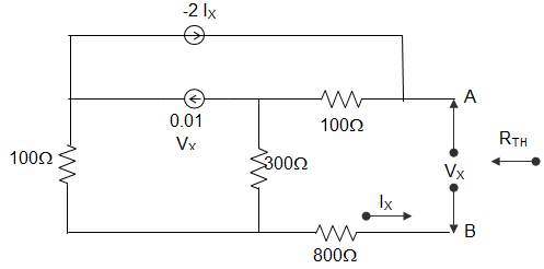
29. For the circuit shown in the figure below, the value of the Thevenin resistance is _________
A. 100 Ω
B. 136.4 Ω
C. 200 Ω
D. 272.8 Ω
30. For the circuit shown in the figure below, the Thevenin voltage and resistance looking into X − Y are __________
A. 4/3 V and 2 Ω
B. 4V and 2/3 Ω
C. 4/3 V and 2/3 Ω
D. 4 V and 2 Ω
Answer: D
RTH = Voc/Isc
VTH = VOC
Applying KCL at node A,
\(\frac{2I − V_{TH}}{1} + 2 = I + \frac{V_{TH}}{2}\)
Or, I = VTH/1
Putting, 2VTH – VTH + 2 = VTH + VTH/2
Or, VTH = 4 V.
∴ RTH = 4/2 = 2Ω.
[/bg_collapse]
31. In the figure given below by using Thevenin’s Theorem find the value of the source voltage is ___________
A. 12 V
B. 24 V
C. 30 V
D. 44 V
32. In the figure given below, the value of Resistance R by the Thevenin Theorem is ___________
A. 10
B. 20
C. 30
D. 40
33. In the figure given below, the Thevenin’s equivalent pair, as seen at the terminals P − Q, is given by __________
A. 2 V and 5 Ω
B. 2 V and 7.5 Ω
C. 4 V and 5 Ω
D. 4 V and 7.5 Ω
34. The Thevenin equivalent impedance Z between the nodes P and Q in the following circuit is __________
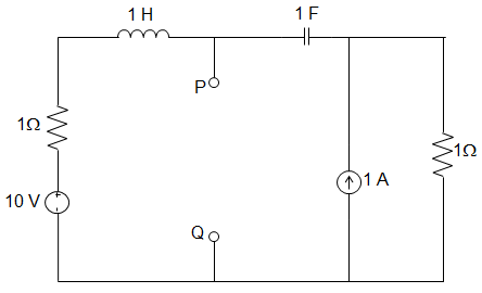
A. 1
B. 1 + s + 1/s
C. 2 + s + 1/s
D. 3 + s + 1/s
35. While computing the Thevenin equivalent resistance and the Thevenin equivalent voltage, which of the following steps are undertaken?
- Both the dependent and independent voltage sources are short-circuited and both the dependent and independent current sources are open-circuited
- Both the dependent and independent voltage sources are open-circuited and both the dependent and independent current sources are short-circuited
- The dependent voltage source is short-circuited keeping the independent voltage source untouched and the dependent current source is open-circuited keeping the independent current source untouched
- The dependent voltage source is open-circuited keeping the independent voltage source untouched and the dependent current source is short-circuited keeping the independent current source untouched