To avoid Fire accident during leakage of transformer oil
To avoid growing of plants and weed
All of the above
4. All of the above
Explanation:
The ground of the substation yard is filled with crushed gravel stones. Generally, 20 to 25 mm baby gravel stones are used instead big size stones to facilitate the movement of persons and equipment in the substation yard. This is because of the following reasons concern to safety from shock:
It provides a high resistance layer or insulation between our feet and the ground. So that the fault currents flow into the ground but not along the ground.
To minimize step potential and touch potential voltages.
It avoids a pool of inflammable oil, etc. on the substation ground in case of any spilling of insulation oil from the equipment. This also avoids spreading free from one equipment to the other in the substation.
It restricts the entering of snakes and other reptiles as the surface would be inconvenient to crawl.
It avoids the growth of plants and weeds in the substation yard to some extent.
Oil leakage takes place during operation or when changing the oil in the transformer. This oil spillage can catch fire is dangerous to the switchyard operation. So Stones is provided to protect from fire when oil spillage takes place.
Qus 32. A transformer on no-load is switched on to a source of voltage. It will draw a current
Which is several times the steady-state magnetizing current depending upon the initial state of the residual flux in the transformer core.
Which is several times the steady-state magnetizing current depending upon the initial state of the residual flux in the transformer core.
Which is the same as the steady-state magnetizing current.
Which is twice the steady-state magnetizing current provided the core has no residual flux.
1. Which is several times the steady-state magnetizing current depending upon the initial state of the residual flux in the transformer core
Explanation:
Whenever a transformer is on no-load,i.e the secondary winding has no burden(load) connected to it.
The transformer must actually withdraw zero current from the primary side.
But practically even on no-load, a small amount of current is drawn from the primary side, to set up the required magnetic flux in the magnetic core.
At no load, the transformer draws some current (Im) in order to establish the flux in the transformer core which lags the applied voltage by 90° (since flux is required to create a magnetic pool in order to transfer energy from one port to another) called as magnetizing current. This magnetizing current (no-load current) is about 3-5% of the full load current and it accounts for the losses in a transformer.
When the transformer is in no-load condition, the primary carries a small no-load current while the secondary current is zero.
However, difficulties arise when an unloaded or lightly loaded transformer is switched on to the supply by closing the breaker at the primary side.
There may be a transient on the primary side immediately after the switching.
The core flux may rise to a very high value (almost equal to twice the normal value) depending on the switching instant, for a few cycles afterward.
This high core flux density drives the core to saturation and the primary winding draws a very large (may be even 7-10 times the rated current) magnetizing current.
In some transformers, this may be as high as 50 to 100 times the normal magnetizing current.
This is the inrush current which decays with time to the small no-load current.
It is not an abnormal situation as the transformer can withstand such a large current for a few cycles without damage.
Qus 33. Cruciform shape is used in the transformer core to
Reduce core loss
Reduce core reluctance
Reduce winding copper
All of the above
4. All of the above Explanation:
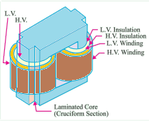
Cruciform transformer
Cruciform core Transformer
Cruciform shape is used in transformer core to reduce core loss, copper, in the winding, reduce core reluctance, and reduction of iron and copper losses.
In a transformer, eddy current losses in the iron core are directly proportional to the core’s thickness. To reduce eddy current loss, we usually use thin sheets of the iron core to reduce the skin effect.
Cruciform or stepped core reduces the diameter of circumscribing. Due to the less diameter, the insulating material required is less and the amount of copper required for winding is reduced. Due to the above reason size, weight, and cost of the Transformer are less with cruciform care.
Qus 34. Which of the following test is performed to determine the leakage reactance
Short circuit test
Open circuit test
Both Open circuit and short circuit test
Test by an Impedance bridge
1.Short circuit test
Explanation:
Short circuit or Impedance test
The short-circuit test is carried out at very low voltage and at the rated full load current. Therefore, the iron loss at that voltage is very low.
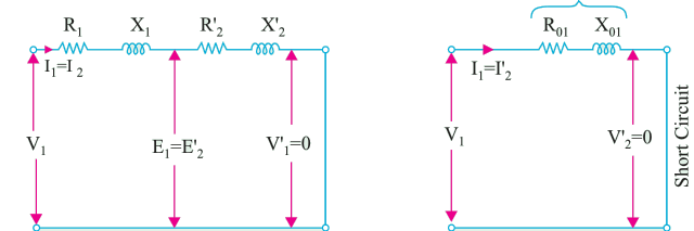
The short-circuit test on the transformer is performed to determine the equivalent resistance and leakage reactance either referred to the primary side or referred to the secondary side. Thus for the performance calculation of a transformer, there is no necessity of determination of the individual parameters of the primary and secondary windings once the equivalent resistance and equivalent leakage reactance are known.
Short circuit test or Impedance test is performed to determine ⇒Copper loss at full load ⇒Equivalent impedance (Zo1 or Zo2) ⇒Leakage reactance (Xo1 or Xo2)
In the short-circuit test, the secondary terminals are short-circuited by a thick conductor, and a reduced voltage is applied until the rated primary current flows. From the measured voltage and current, we can calculate the leakage inductance.
A short circuit test is performed on the HV side of the transformer.
Low voltage (5 to 10%) is applied to the primary and slowly increases till full load current is flowing both in primary and secondary.
The ammeter reading gives full load current IL.
Since applied voltage is small so flux (Φ) is also small therefore core loss is small hence core loss can be neglected.
[/bg_collapse]
Qus 35. During SC test the Power Input to a transformer comprises predominately
Core loss
Copper loss
Hysteresis loss
Eddy current loss
2. Copper loss
Explanation: (For more detail check previous question)
Short circuit or Impedance test
Short circuit test or Impedance test is performed to determine
⇒ Copper loss at full load
⇒ Equivalent impedance (Zo1 or Zo2)
⇒ Leakage reactance (Xo1 or Xo2)
The figure shows the circuit diagram for conducting the short-circuit test on a transformer. One of the windings of the transformer is short-circuited through an ammeter, while a low voltage is applied to the other winding.
The applied voltage is slowly increased until full load current flows in this winding. The full load current will then flow in the other winding also.
Normally the applied voltage is hardly 5 to 7 percent of the rated voltage of this winding. As such the flux established in the core will be quite small and so the iron losses occurring under this condition is negligible.
Thus, the reading indicated by the wattmeter connected in the circuit gives the full load copper losses of the transformer.
Qus 36. The maximum load that a power transformer can carry is limited by its
Voltage ratio
Temperature Rise
Cooper Loss
Dielectric strength of coil
Ans 2. Temperature Rise
Explanation:
The amount of power a transformer can transfer depends primarily on the magnetic properties and the volume of its core.
This power is frequency-dependent and it scales essentially with P ∝ V ∝ F.
For a given core size and core material (which also depends on the application), the number of turns then determines the inductance and the capacitance of the primary and secondary coils.
The capacity of a transformer is in KVA or MVA. Its voltage and current ratings are fixed for a particular transformer.
The kVA capacity of a transformer is the output that it can deliver for a specified period of time, at the rated secondary voltage and rated frequency, without exceeding a specified temperature rise based on insulation life and ambient temperature.
Transformers can be loaded above their kVA ratings with no loss of life expectancy only when operated within the manufacturer’s stated limits. Select the transformer based on its kVA capacity and temperature rating.
The rated kVA capacity is based on the maximum current delivered at rated voltage.
The real limit in the transformer’s capability is the amount of current that it can provide without exceeding a defined temperature rise.
Qus 37. A shell-type transformer has
High eddy current losses
Reduce magnetic leakage
Low hysteresis losses
All of the above
Ans 2. Reduce magnetic leakage
Explanation:
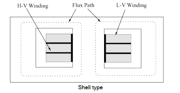
Shell Type Transformer
When the primary and secondary windings are encircled by the magnetic material, the transformer is referred to as a shell-type transformer.
In shell-type construction, there are two parallel magnetic paths into which the flux from the central limb can divide.
The primary and secondary windings are wound on the central limb one above the other. This provides a better magnetic coupling between the primary and secondary windings and reduces the magnetic leakage from the core.
Shell-type transformer construction features a short magnetic path and a longer mean length of the electrical turn.
The shell-form transformer has a larger core area and a smaller number of winding turns than the core-form of the same output and performance.
Additionally, the shell form generally has a larger ratio of steel to copper than an equivalently rated core-form transformer.
The core type has a longer mean length of the magnetic flux but a shorter mean length for the winding coils and so it is better suited for very high voltage transformers which require a large number of turns in their windings and also, it offers better scope for insulation and its inspection.
Qus 38.A transformer can have zero voltage regulation closer to zero
On full load
On overload
On leading power factor
On zero power factor
Ans 3. On Leading power factor
Explanation:
Voltage regulation is defined as the ratio of the difference between no-load voltage and full load voltage to no-load voltage. Voltage regulation depends on the nature of the load.
For lagging and unity power factor V2 > E2. where, V2 = Secondary terminal voltage on a given load. E2= Secondary terminal voltage on no load.
As the load increase, it tends to become capacitive and V2 start increasing.
In case the load has a leading power factor, the voltage drop is less than what it is in the case of the unity power factor load. If the effect of voltage drop due to resistance is exactly balanced by the voltage drop due to reactance, it is possible to have V2 = E2, i.e., the voltage on load remains the same as the voltage on no-load, and regulation becomes zero.
In leading, the power factor condition load is just able to supply the reactive power for the active power flow.
In a transformer, minimum voltage regulation occurs when the power factor of the load is leading.
The voltage regulation of the transformer is zero at a leading power factor load such as a capacitive load.
Qus 39. Natural air cooling is generally restricted for transformer upto
1.5 MVA
5 MVA
15 MVA
20 MVA
Ans 1.1.5 MVA
Explanation:
Air natural cooling method:
The natural air cooling method is also known as the self-cooled method.
In this method, the heat generated by the transformer is cooled by the circulation of natural air.
It is used for small voltage transformers.
Due to the available insulating materials like glass and silicon resins nowadays, the method can be used for the transformers upto ratings 1.5 MVA.
Beyond that level, natural air cooling is not very effective and the transformer can be heated upto a dangerous level which can cause serious damage to the transformer.
Qus 40. The size of the transformer core mainly depends on
Frequency
Area of core
Flux density of core
Both frequency and area of core
Ans. 4 Both frequency and area of core
Explanation:
From emf equation of transformer
$E = 4.44fNAB$
Where E= Voltage f= frequency A= Area of the core N= number of turns B =magnetic flux density
In general, we can say
A = E/(4.44fNB)
For the constant value of E, N, B if we increase F, then the Area of the core will decrease means the size of the transformer will reduce.
The Frequency is inversely proportional to the A-area of the Transformer. As the Frequency is High, the Size and Weight of the Transformer of the same power Rating can be reduced.
Higher frequency implies faster MMF variations with time hence higher emf is inducted on coils, then for same voltage lower core area is needed or lower number of turns, in any case, lower volume.
The flux is proportional to the ratio of voltage/frequency. The higher the frequency lower is the flux in the transformer and vice versa. So, at higher frequencies the operating flux in the transformer core is low. That means there is no point in using a lot of magnetic material in the core to handle that flux which reduces the size of a transformer.
But if we operate a transformer at low frequencies the build has to be a big one. Large flux would need a larger core thus increasing the size of a transformer.