Ques 41. The transformer oil should have _____ Volatility and _____ Viscosity.
Low & High
High & High
Low & Low
High & Low
Ans 3. Low & Low
Explanation:
The transformer oil should have low Volatility and low Viscosity.
Viscosity- The ease with which this convection flow can be induced clearly is very dependent on the viscosity of the fluid and it is therefore important for a transformer oil to have a low viscosity.
Low viscosity will assist in the penetration of oil into narrow ducts and assist in the circulation through windings to prevent local overheating which would result from poorer flow rates in the less accessible areas. Therefore transformer Oil having low viscosity i.e greater fluidity will cool transformers at a much better rate.
Mineral oils, like most other fluids, increase in viscosity as their temperature is reduced until they become semi-solid, at which stage their cooling efficiency is virtually nil. The pour point of a fluid is the lowest temperature at which the fluid is capable of any observable flow. For many transformers used in cold climates, the oil must not approach this semi-solid condition at the lowest temperatures likely to be experienced and so the oil must have a low pour point.
Volatility:- Normally transformers are expected to have a life of at least 30 years. It is desirable not to have to constantly think of making good evaporation losses during this lifetime, nor is it acceptable that the composition of the oil should change due to the loss of its more volatile elements. Low volatility is therefore a desirable feature. Volatility is quantified by the tendency of a substance to vaporize. Volatility is directly related to a substance’s vapor pressure. At a given temperature, a substance with higher vapor pressure vaporizes more readily than a substance with lower vapor pressure
It will be recognized that fire and explosion are to some extent potential risks whenever petroleum oils are used in electrical equipment. It is, therefore, necessary that the temperature of the oil in service should be very much lower than the flashpoint.
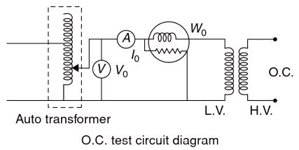
Ques 42. During the open circuit test of a transformer
The current drawn by shunt parameters in a transformer is a no-load current. Therefore the current that will flow in the circuit in the open circuit test is very low so the measurement of the quantities voltage, current, and power must be on the low voltage side so that the corresponding value will be readable in the instruments. And therefore, the open circuit test must be performed on the low voltage side. This means the high voltage side must be kept open. The current drawn from the open circuit test is the no-load current at a low power factor corresponding to the core loss component.
As the normal rated voltage is applied to the primary, therefore, normal iron losses will occur in the transformer core. Hence wattmeter will record the iron losses and small copper loss in the primary. Since the no-load current is very small (usually 2 — 10% of rated current), Cu losses in the primary under no-load conditions are negligible as compared with iron losses. Hence, wattmeter reading practically gives the iron losses in the transformer It is reminded that iron losses are the same at all loads.
Ques 43. Which type of winding is used in a 3-phase shell type transformer?
Rectangular Type
Cylindrical Type
Sandwich Type
Circular type
Ans 3.Sandwich Type
Explanation:
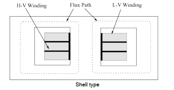
Shell Type Transformer
When the primary and secondary windings are encircled by the magnetic material, the transformer is referred to as a shell-type transformer.
In shell-type construction, there are two parallel magnetic paths into which the flux from the central limb can divide.
The primary and secondary windings are wound on the central limb one above the other. This provides a better magnetic coupling between the primary and secondary windings and reduces the magnetic leakage from the core.
In the case of shell-type transformers, sandwich-type windings are used.
The high voltage and low voltage windings are split into a number of sections where each high voltage section lies between two low voltage sections. Such type of sandwich windings is shown in Fig.
Shell-type transformer construction features a short magnetic path and a longer mean length of the electrical turn.
The shell-form transformer has a larger core area and a smaller number of winding turns than the core-form of the same output and performance.
Additionally, the shell form generally has a larger ratio of steel to copper than an equivalently rated core-form transformer.
The core type has a longer mean length of the magnetic flux but a shorter mean length for the winding coils and so it is better suited for very high voltage transformers which require a large number of turns in their windings and also, it offers better scope for insulation and its inspection.
Ques 44. The transformer laminations are insulated from each other by
Mica strip
Paper
Thin coating of Varnish
Any of the above
Ans 3. Thin coating of Varnish
Explanation:
The magnetic core of the transformer is made up of laminated silicon steel. The silicon steel material is used to decrease the hysteresis loss. The thickness of the lamination varies from 0.3 to 0.5 mm. In order to reduce the eddy current losses, the thickness of laminations should be very small. The laminations are insulated from each other by using insulation like varnish. When requiring a varnish for a winding application, bond strength, application, build (thickness), temperature class and chemical resistance must be determined.
The purpose of providing the coating of varnish in windings are
Bonding the magnet wire together to form a hard structure, which provides a degree of mechanical strength.
Adding additional insulation to the winding system preserves the initial dielectric strength of the insulation to which it is applied.
The extra insulation allows the winding to withstand higher voltage stress levels without damage.
Sealing the winding to resist contaminants such as moisture, dust, fungus, and chemicals.
Filling the voids (displacing the air – that is, a thermal barrier) in the slots of electrical apparatus, between layers of insulation and winding turns.
To promote the conduction of heat from the center of windings to the exterior environment via a low thermal resistance path and so keep the winding temperature down.
A reduced winding temperature means lower electrical resistance and therefore less copper (I2R) losses.
To reduce mechanical vibrations and the audible noise level of the apparatus.
Ques 46. Two transformers are connected in parallel. These transformers have different percentage impedance. It is likely to result in
Loading in the transformer is not proportional to their KVA rating.
Short circuit in secondary
Higher copper loss
Power factor of one of the transformer is leading while that of the other is lagging.
Ans 1. Loading in the transformer is not proportional to their KVA rating.
Explanation:
Parallel operation of transformers
There are a number of requirements that must be satisfied before two or more single-phase transformers can be ‘paralleled -i.e. before they can be connected in parallel with each other, in order to supply the same load. These requirements are
Same voltage ratio (turns ratio)
Similar percentage impedance
Similar kVA rating
Same polarity
Similar percentage impedance:-
A transformer’s percentage impedance can be determined by shortcircuiting the secondary winding with an ammeter, and gradually increasing the primary voltage until rated current flows in the secondary.
The percentage impedance is then simply the ratio of that particular primary voltage to the rated primary voltage, expressed as a percentage.
In other words, the per-unit or percentage impedance of the two transformers should be equal. If this condition is fulfilled, load sharing of the total connected load between the two transformers will be proportional to their kVA ratings.
So, for example, if a particular transformer has a percentage impedance of, say, ‘5%’, then it would take just 5% of the rated primary voltage to cause 100% of the rated secondary current to flow through the short-circuited secondary winding.
For unequal ratings, the numerical (ohmic) values of their impedances should be in inverse proportion to their ratings to have current in them in line with their ratings.
If the transformer does not have equal percentage impedance then the loading of the transformer is not in proportion to their kVA rating.
A difference in the ratio of the reactance value to the resistance value of the per-unit impedance results in a different phase angle of the currents carried by the two paralleled transformers; one transformer will be working with a higher power factor and the other with a lower power factor than that of the combined output.
Hence, the real power will not be proportionally shared by the transformers.
Ques 47. Which of the following is the main advantage of an autotransformer over a two winding transformer?
Reduces hysteresis losses
Reduce eddy current losses
Copper losses are negligible
Saving of copper material
Ans 4. Saving of copper material
Explanation:
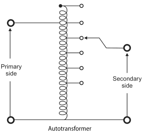
An autotransformer is a type of transformer that uses a single tapped winding rather than the two separate and electrically isolated windings used by mutual transformers. Because autotransformers don’t have separate windings, unlike mutual transformers there is no electrical isolation between the primary and secondary circuits.
Therefore the primary is electrically connected to the secondary, as well as magnetically coupled to it.
The alternating current applied between the input points will induce a flow of magnetic flux around the core.
This magnetic flux will link with all the turns forming the coil, inducing a voltage into each turn of the winding.
Since the volts-per-turn is the same in both windings, each develops a voltage in proportion to its number of turns.
In an autotransformer, part of the current flows directly from the input to the output, and only that part is transferred.
Where electrical isolation between the primary and secondary windings is unimportant, the use of an autotransformer has a number of advantages over a mutual transformer.
As we know that, the saving of copper in auto-transformer is “K” times the copper required in the 2-winding transformer. Hence less copper is required in the case of an auto-transformer.
As less copper is required, hence less ohmic losses and core losses will occur. Correspondingly the efficiency of an auto-transformer is higher than the efficiency of a 2-winding transformer.
Leakage reactance is less in the case of an auto-transformer, hence it has superior voltage regulation.
Due to single winding, less weight as well as less space will be there.
There are no secondary copper losses, so autotransformers are more efficient than a corresponding mutual transformer.
Qus 48. Which winding of the transformer has less cross-sectional area?
Primary winding
Secondary Winding
High Voltage Winding
Low Voltage Winding
Ans 3. High Voltage winding
Explanation:
The number of turns on the primary and secondary windings depends upon their respective voltages.
We know that current density is defined as the ratio of current to perpendicular cross-section area through which current is crossing.
The value of current density of HV winding is more in comparison to LV winding because of better cooling of HV winding
Since HV winding is placed far from the core in Comparison to LV winding which is placed near to the core.
Current density is inversely proportional to the area of the core so the thin wire is used for HV winding.
Also as the resistance of winding is inversely proportional to the area of cross-section, the area of high voltage winding is less compared to low voltage winding.
Therefore HV winding has Low cross-sectional area.
A high-voltage winding has far more turns than a low-voltage winding.
On the other hand, the current in a high-voltage winding is much smaller, enabling us to use a smaller size conductor.
The result is that the amount of copper in the primary and secondary windings is about the same.
Ques 49. The core used in the high-frequency transformer is usually
Copper Core
Iron Core
Mild Steel Core
Air core
Ans. 4 Air Core
Explanation:
Transformer core
Air core transformer- This transformer has no iron core. It consists of simply two insulated primary and secondary coils placed closely one to the other.
Open core transformer:- In this transformer, the primary and secondary coils are each separately wrapped around their own ferromagnetic cores. Again both coils+cores are placed close to each other. Some auto- transformers are open-core type transformers (both insulated coils are wrapped around a single iron core).
Closed core transformer (most often used):- In this transformer, the primary and secondary coils are wrapped around an iron core with closed geometry (either a ring or square shape).
From the application parameters point of view, the type of a transformer core depends on operational factors such as applied voltage, current, and frequency.
In addition to these, size limitations and construction costs are further factors to be considered. Conventionally applied core materials are air, soft iron, and steel.
Generally, air-core transformers are used when the voltage source has a higher frequency above 20kHz
Iron-core transformers are usually used when the source frequency is below 20kHz.
Transformer cores composed of laminated steel sheets isolated with a nonconducting material provide the highest efficiency among conventional core materials primarily due to better dissipation of heat generated during the process.
Iron becomes less effective as a magnetic circuit because at high frequencies, the fluX penetrates to lesser extent in the core
Qus 50. Harmonics in transformer results in
Increase core losses
Increases I2R Losses
Interference with communication circuits
All of the above
Ans 4. All of the Above
Explanation:
The term harmonic is derived from acoustics and is defined as the content of the electrical signal whose frequency is an integral multiple of fundamental or system frequency produced by generators.
Transformer as Source of Harmonics
Transformers can be considered as sources of harmonic voltages, which arise from magnetic distortion and magnetic saturation due to the presence of a DC component in its secondary. The magnitude of these harmonics depends upon the operating flux density. Converter transformers are usually operated at high flux densities than conventional 3-phase transformers, and therefore the possibility of generation of harmonics is more in the former than in the later.
Effects of Harmonics on Transformers
Harmonics have an effect on transformers in various ways
Core loss: Harmonic voltage increases the hysteresis and eddies current losses in the laminations. The amount of the core loss depends on the harmonics present in the supply voltage design parameter of core materials and magnetic circuits. Eddy current losses are of large concern when harmonic current is present in the network. These losses increase approximately with the square of the frequency. Total eddy current losses are normally about 10% of the losses at full load.
Hysteresis loss: Hysteresis loss increases because voltage harmonics set up the hysteresis loop on the fundamental loop. So each loop represents a higher magnetization power requirement and higher core losses in the transformer.
Copper loss: Harmonic current increases copper loss. The loss (I2R,) mainly depends on the harmonics present in the load and the effective ac resistance of the winding. Copper loss increases temperature and creates hot spots in that transformer. The effect is prominent in the case of converter transformers these transformers do not benefit from the presence of filters as filters are normally connected on the a.c. system side.
Stress: Voltage harmonics increase the stresses of the insulation.
Core vibration: Current and voltage harmonics increase small core vibration.
Saturation problem: Sometimes additional harmonic voltage causes core saturation.
Interference in communication line:- The third harmonic current may cause interference in the communication circuit running parallel to power lines. If a tertiary delta winding is provided, the third harmonic currents will be reduced but not completely eliminated.