Ques.81. In which type of windings extra insulation between layers is required in addition to the insulation of conductors.
Cross over windings
Continuous disc windings
sandwich windings
Helical windings
Answer.4. Helical Winding
Explanation:-
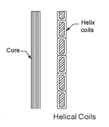
Helical Winding: The helical coils cover the intermediate range of current which falls between the range of high current range of spiral coils and the low current range of multi-conductor disc coil. This coil is wound in the form of a helix where each conductor may consist of a number of rectangular strips wound in parallel radially. Helical winding is mostly suitable for low-voltage (11 kV to 33 kV) windings of large transformers. In general, simple single-layer helical coils are used for the LV side of large transformers. The cross-sectional view of a typical single-layer helical coil is shown in Fig. However, multiplayer helical coils may be used for high-voltage windings.
They can also be used for high voltage windings by putting extra insulation between layers in addition to the insulation of conductors.
Ques.82. A 2 kVA transformer has an iron loss of 150 W and a full load copper loss of 250 W. The maximum efficiency of the transformer will occur when the total loss is:
500 W
400 W
300 W
275 W
Answer.3. 300 W
Explanation
The efficiency of a transformer will be maximum when copper losses are equal to iron losses. Iron losses include both hysteresis and eddy current losses.
Copper losses = 250 W
Iron losses = 150 W
At maximum efficiency, copper losses = 150 W
Total losses = 150 + 150 = 300 W
Ques.83. A single-phase 100 kVA, 1000 V / 100 V, 50 Hz transformer has a voltage drop of 5% across its series impedance at full load. Of this, 3% is due to resistance. The percentage regulation of the transformer at full load with 0.8 lagging power factor is
4.8
6.8
8.8
10.8
Answer.1. 4.8
Explanation:-
Given that,
Voltage drop across series impedance (% Z) = 5%
Voltage drop due to resistance (% R) = 3%
Power factor = 0.8 lagging
We know that, $ %Z=\sqrt{(%R)^{2} +(%X)^{2}}$
$ %X=\sqrt{(%R)^{2} -(%Z)^{2}}$
$ X=\sqrt{(5)^{2} -(3)^{2}}$ = 4%
Voltage regulation = %R cos ϕ ± %X sin ϕ
+ve is for lagging loads
-ve is for leading loads
Voltage regulation = (3) (0.8) + (4) (0.6) = 4.8%
Ques.84. The hysteresis loss in a given magnetic material may be decreased by
Laminating it
Decreasing maximum flux density established through it
Increasing frequency of reversal of magnetization
Increasing flux density through it
Answer.2. Decreasing maximum flux density established through it
Explanation:-
Hysteresis losses are also known as Iron Loss or Core Loss and it is always constant.
Hysteresis loss is due to the reversal of magnetization of the transformer core whenever it is subjected to the alternating nature of magnetizing force. The power consumed by the magnetic domains for changing the orientation after every half cycle is called Hysteresis loss.
Wh = η × Bm1.6 × f × V
Where, η is Steinmetz constant
f is frequency
Bm is the magnetic flux density
V is the volume of the core
Wh = hysteresis loss
∴ The hysteresis loss in a given magnetic material can be decreased by decreasing the maximum flux density established through it
Ques.85. In a transformer, the core loss is found to be 46 W at 50 Hz and is 80 W at 70 Hz, both losses being measured at the same peak flux density. The hysteresis loss and eddy current loss at 60 Hz is
11 W, 20 W
30 W, 45 W
16 W, 30 W
22 W, 40 W
Answer.4. 22 W, 40 W
Explanation
Core loss = Eddy current loss + Hysteresis loss
= Kef2 + Kcf
At 50 Hz, Pc = 46 watt
46 = Ke (50)2 + Kh x 50………. 1
At 70 Hz, Pc = 80 watt
70 = Ke (70)2 + Kh x 70…………… 2
From equation (1) and (2),
Ke = 0.0111
Kh = 0.363
Now at 60 Hz,
Pe = Ke x 602
= 0.0111 x 3600 = 39.96 ≅ 40 Watt
Ph = 0.36306 x 60
= 21.78≅ 22 Watt
Ques.86. The maximum flux density in the core of a 250/3000 Volts, 50 Hz, 1 = ph transformer is 1.2 wb/m2. Determine the LV and HV turns of the transformer if the emf per turn is 8 V.
NLV = 64, NHV 750
NLV = 375, NHV = 32
NLV = 32, NHV = 375
NLV = 750, NHV = 64
Answer.3. NLV = 32, NHV = 375
Explanation:-
In a transformer, the relation between the number of turns, current, and voltages is given by:
N1/N2 = V1/V2 = I2/I1
N1 ∝ V1 & N2 ∝ V2
N1 and N2 = number of turns in the primary and secondary windings respectively
V1 and I1 = Voltage and current respectively at the primary end
V2 and I2 = Voltage and current respectively at the secondary end
Calculation:
V1 = 250 V = LV side voltage,
V2 = 3000 V = HV side voltage,
EMF or voltage per turn = 8 V
The number of LV turns of the transformer is
N1 = NLV = 250/8 = 32
The number of HV turns of the transformer is
N2 = NLV = 3000/8 = 375
Ques.88. Impulse testing of transformers is done to determine the ability of
Bushings to withstand vibrations
Insulation to withstand transient voltages
Windings to withstand voltage fluctuations
All of the above
Answer.2. Insulation to withstand transient voltages
Explanation:-
The purpose of the impulse test is to determine the ability of the insulation of the transformers to withstand the transient voltages due to lightning, etc. It is well known that power system components are subjected to severe overvoltage due to internal switching or external lightning surges. Since the transients are impulses of short rise time, the voltage distribution along the transformer winding will not be uniform.
In addition to the verification of dielectric strength of transformer insulation, impulse tests indicate the quality of insulation, processing, and workmanship. The dielectric test alone cannot determine the dielectric strength of the insulator (for all the frequencies).
Impulse testing of transformers is done using both the full-wave and the chopped wave of the standard impulse, produced by a rod gap u ith a chopping time of 3 to 6 µs. To prevent large overvoltages from being induced in the windings, not under test, they are short-circuited and connected to the ground. But the short-circuiting reduces the impedance of the transformer and hence poses problems in adjusting the standard waveshape of the impulse generators. It also reduces the sensitivity of detection.
Ques.89. In transformers, which of the following statements is valid
In an open circuit test, copper losses are obtained while in short circuit test, core losses are obtained
In an open circuit test, current is drawn at high power factor
In a short circuit test, current is drawn at zero power factor
In an open circuit test, current is drawn at low power factor
Answer.4. In an open circuit test, the current is drawn at the low power factor
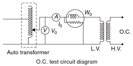
The current drawn by shunt parameters in a transformer is a no-load current. Therefore the current that will flow in the circuit in the open circuit test is very low so the measurement of the quantities voltage, current, and power must be on the low voltage side so that the corresponding value will be readable in the instruments. And therefore, the open circuit test must be performed on the low voltage side. This means the high voltage side must be kept open. The current drawn from the open circuit test is the no-load current at a low power factor corresponding to the core loss component.
As the normal rated voltage is applied to the primary, therefore, normal iron losses will occur in the transformer core. Hence wattmeter will record the iron losses and small copper loss in the primary. Since the no-load current is very small (usually 2 — 10% of rated current), Cu losses in the primary under no-load conditions are negligible as compared with iron losses. Hence, wattmeter reading practically gives the iron losses in the transformer It is reminded that iron losses are the same at all loads.
Ques.90. In an open circuit, a converter of 11 KVA 1100/110 V outputs 100 W of power when 110 V is applied to an LV winding with an open HV winding. If 1100 V is applied on HV winding with open LV winding, what will be the power input?
10000 W
1000 W
100 W
10 W
Answer.3. 100 W
Explanation
Formula:
W0 = wattmeter reading
V1 = voltmeter reading
I0 = Ammeter reading
cosϕo = No load power factor.
∴ Iron loss of the transformer, Pi = W0
W0 = V1 I0 cosϕ0
No-load power factor = cosϕ0 = W0/V1 I0
Working component or core loss component,
IW = I0 cos ϕ0
When LV side is given supply and HV winding is open
power is drawn = 100 W
When the HV side is given supply and LV winding is open
Power is drawn = 100 W
This is because the no-load test can be performed on any winding side and the reading remains same. But preferred is on the LV side.