
Transformer MCQ
Qus1. The secondary winding of which of the following transformers is always kept closed?
- Current transformer
- Voltage transformer
- Power transformer
- Step down transformer
Answer.1. Current Transformer Explanation. The secondary winding of current transformers is always kept closed. If the current transformer secondary is not shorted when unused and kept open then it can develop a very high voltage across secondary which may damage transformer insulation. Detail Explanation:- Instrument transformers are used in conjunction with an ammeter and voltmeter to extend the range of meters. In dc circuit shunt and multipliers are used to extend the range of measuring instruments. The shunt is used to extend the range of the ammeter whereas the multiplier is used to extend the range of voltmeters This type of ammeter is shown in Figure. The primary of the transformer is connected in series with the load, and the ammeter is connected to the secondary of the transformer. Notice that the range of the meter is changed by selecting different taps on the secondary of the current transformer. The different taps on the transformer provide different turn-ratios between the primary and secondary of the transformer. The working of the current transformer is explained in detail.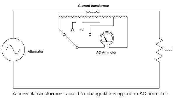
Qus2. If the supply frequency of a transformer increases, the secondary output voltage of the transformer
- Increase
- Decrease
- Remain the same
- Any of the above
Answer.1. Increase Explanation: The EMF Equation Of A Transformer is given by $E = 4.44fBNA$ where E = the voltage in the winding either primary or secondary, A transformer is designed for some constant parameters like frequency. So if the frequency increases, the secondary voltage or emf increases. But with high frequency, there is an increase in transformer losses like core loss and conductor skin effect. Also with high frequency, the magnetizing current becomes low and with low frequency the magnetizing current becomes high. The higher the input frequency, the higher will be the rate of change of magnetic flux, which results in higher induced EMF Frequency ~ Rate of Change of Magnetic Flux ~ Induced EMF Note:- There are some other conditions which should be kept in mind Condition 1:- If you are maintaining the same voltage but higher frequency, flux ( V/f ) in the transformer falls, the induced emf would hence remain the same and would not increase. Although the rate of change of flux increases due to increased frequency but the value of flux is reduced and hence the overall effect is that voltage induced in the secondary remains the same but at a higher frequency of course. Condition 2:- If you are increasing primary voltage along with increasing frequency so as to maintain constant flux, only in that case the secondary voltage will increase. Therefore you can safely conclude that secondary voltage depends only upon the primary voltage and turns ratio.
f = frequency
B = flux density in the core
N = Number of turns on the winding
A = Cross area of the core
Qus3. Power transformers are designed to have maximum efficiency at
- Full load
- 50% load
- 80% load
- no load
Answer.1. Full load Explanation: Transformers of the large size used in generating stations at the sending end of the transmission line to step up the voltage and at the receiving end of the transmission line to step down the voltage is known as power transformers. A number of such transformers are connected in parallel. They are operated up to full-load capacity by connecting or disconnecting transformers depending upon the load condition. Power transformers are mostly used near full load conditions and hence designed for maximum efficiency at or near full load. Power transformers are used for transmission as a step-up device hence they are not directly connected to consumers therefore, load fluctuation is very less. So the power transformer can operate on full load. Distribution transformers are comparatively smaller transformers of rating of the order of hundreds of KVA and are connected directly to supply the load at 400/230 volts. Thus, the secondary side of a distribution transformer is directly connected to the load. They are to be kept in operation all the time for all the days irrespective of whether the consumer is utilizing the power or not. Thus, the load on a distribution transformer varies throughout the day depending upon how the consumers utilize the load. The average load on a distribution transformer is much less than its rated capacity. That is why they are rated to have maximum efficiency at a load lower than their full-load capacity. They are designed to have good all-day efficiency rather than the highest efficiency at or near full-load.
Qus4. The open-circuit test in a transformer is used to measure
- Copper loss
- Winding loss
- Total loss
- Core loss
Answer 4. Core loss Explanation: The purpose of the open-circuit test’ is to determine the excitation admittance of the transformer- equivalent circuit, the core loss, the no-load excitation current, and the no-load power factor. The figure shows the connections for the open-circuit test. The low voltage winding is supplied with the rated voltage which should result in the rated voltage on the high voltage side. The current drawn should be low enough so that the copper losses are very low and the power measured 1s almost all from the core losses. The current drawn during the open Circuit test will be the excitation current.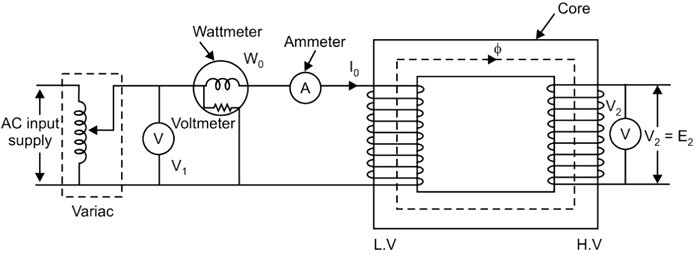
Qus5. The leakage flux in a transformer depends upon the value of
- Frequency
- Mutual Flux
- Load current
- Applied Voltage
Answer 3. Load Current Explanation: Leakage flux:- The flux that escapes from the core and flux that passes through one winding only.
Qus6. Lamination of the transformer core is made of
- Cast Iron
- Silicon Steel
- Aluminum
- Cast Steel
Answer 2. Silicon Steel Explanation: Silicon steels are used for electrical transformer cores and cores of other electrical devices for the following reasons:- The function of a transformer’s core is to provide a low-reluctance/high permeability magnetic circuit by which magnetic flux, created by the magnetomotive force in the primary winding, can efficiently couple with the secondary winding. Transformer cores are manufactured from a silicon-iron alloy (iron with around 3% silicon content), which is more generally termed ‘silicon steel, ‘electrical steel’, ‘transformer steel’, or by some trade name such as ‘Stalloy’. This ferromagnetic alloy is specifically designed to have all of the characteristics described. ⇒ Low-reluctance/high permeability magnetic circuit, in order to maximize the flux density within the core. ⇒ Low-remanence/low-coercivity/low-area hysteresis loop: To minimize the energy loss per magnetization/demagnetization cycle; this energy loss being termed its ‘hysteresis loss’ ⇒ High resistivity conducting path: To minimize any ‘eddy currents’ (circulating currents) resulting from undesirable voltages induced into the core; eddy currents are further minimized by manufacturing the core from laminations. The silicon content of the iron acts to both reduce the core’s hysteresis losses and to increase its resistivity by a factor of around 4.5, which acts to reduces the magnitude of any circulating currents (eddy currents) that result from voltages induced into the core. There are two general categories of silicon-steel, termed ‘grain orientated steel‘ and ‘non-orientated steel‘: ⇒ Grain-orientated steel has a silicon content of around 3% and is manufactured in such a way that its magnetic properties are optimized along the direction of its grain, enabling its flux density to be increased by as much as 20% in that direction. ⇒ Non-orientated steel, with a silicon content of 2-3.5%, has a randomly orientated grain with similar magnetic properties in all directions, but the resulting flux density can be significantly lower than for grain-orientated steel. From the point of view of the varying flux, the core of a transformer is simply another winding and, therefore, it will induce a voltage into it. If the core was manufactured from a solid piece of silicon steel, then it would behave like a heavy, short-circuited, single winding, and a large current would circulate around it. In eddy current, the magnetic field that induces a voltage in the secondary of a transformer also induces a voltage in the core. This causes circulating (or eddy currents) in the core. Making the laminations as thin as possible reduces this loss. The laminations are coated with a thin insulating material to prevent current from flowing between them.
Qus7. Breather is provided in a transformer to
- Absorb moisture of air during breathing
- provide cold air in the transformer
- The filter of transformer oil
- None of above
Answer 1. Absorb moisture of air during breathing. Explanation: Transformer oil should not be exposed directly to the atmosphere because it may absorb moisture and dust from the environment and may lose its electrical properties in a very short time. To avoid this problem a breather is provided on the top of the conservator. Breather is the heart of the transformer, which is similar to the human heart. The breather transports fresh air in and out of the transformer. This component is required to maintain the cooling-medium level in the conservator. Breather mainly consists of a silica gel. The silica gel absorbs the moisture content of air so that oil contamination can be prevented. The silica gel which is blue in color turns pink when it absorbs moisture fully. it is replaced periodically as routine maintenance.
Qus8. Which of the following losses varies with the load in the transformer?
- Core loss
- Copper loss
- Both core & copper loss
- None of the above
Answer 2. Copper Loss Explanation:
Qus9. A transformer transform
- Current
- Voltage & current
- Frequency
- Voltage
Answer 2. Voltage & Current Explanation: A transformer is a static device that is used to convert the voltage or current to a higher (step-up) or lower (step down) level. The Distribution Transformer, Auto Transformer, and Tap changing Transformer basically belong to the family of Power Transformer with respective unique features. In an Instrument Transformer, voltage or current on one side of the transformer, comparatively high (therefore not suitable for direct measurement), is scaled down to voltage or current to levels that is convenient for measurement with suitable instrumentation. Accordingly, the two types of Instrument Transformers are the Current Transformer and the Potential Transformer. Some applications may call for constant current (as in welding) or constant voltage. Such transformers am called Constant Current and Constant Voltage Transformers.
Qus10. Transformer core are laminated in order to
- Reduce hysteresis loss
- Reduce hysteresis & eddy current loss
- Minimize eddy current loss
- Copper loss
Answer 3. Minimize Eddy current loss Explanation: High resistivity conducting path: To minimize any ‘eddy currents’ (circulating currents) resulting from undesirable voltages induced into the core; eddy currents are further minimized by manufacturing the core from laminations.
